How Can We Help?
Pocket Shield
1. motor [fieldMenu_1]rotates at power [number_2] %

Rotates the output shaft(s) of the motor(s) connected to the specified port(s) clockwise at the specified power
How to use
The pocket shield for CyberPi provides two DC motor ports, M1 and M2.
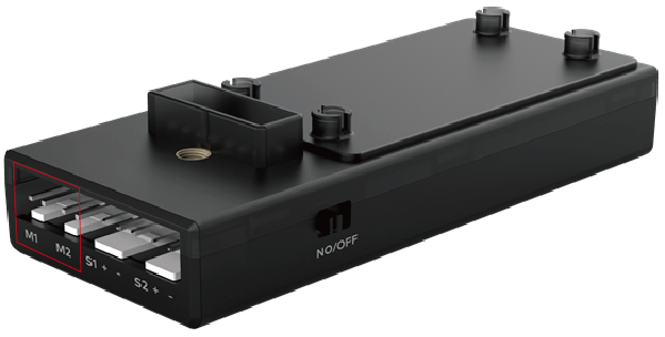
Click to select a motor or both motors from the drop-down list box and set the power.
Setting range of the power: –100 to +100%
A positive value indicates that the output shaft of the motor rotates clockwise, and a negative one indicates that the output shaft of the motor rotates counterclockwise.
Example
Connect two motors through ports M1 and M2 of the pocket shield.
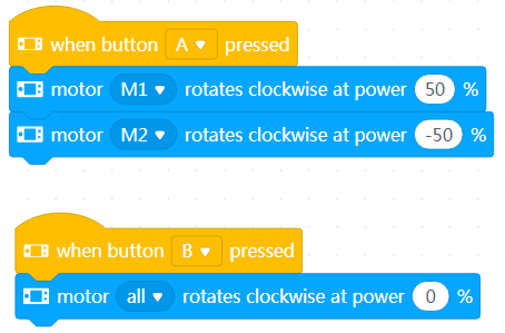
When you press button A, the output shafts of the two motors rotate; and when you press button B, they stop rotating.
Note: You can assemble the two motors on a car robot to drive the wheels before connecting them to CyberPI and then use this example program to control the motion of the car robot.
2. motor[fieldMenu_1]rotates, increasing power[power] %

Changes the power of the output shaft(s) of the motor(s) connected to the specified port(s) by the specified amount for rotating clockwise
How to use
The pocket shield for CyberPi provides two DC motor ports, M1 and M2.
Click to select a motor or both motors from the drop-down list box and set the amount by which the power is to be changed.
Setting range of the power: –200 to +200%
A positive value indicates increasing, and a negative one indicates decreasing.
Example
Connect two motors through ports M1 and M2 of the pocket shield.
When you press button A, the output shafts of the two motors rotate; when you move the joystick up, they speed up; and when you press button B, they stop rotating.
Note: You can assemble the two motors on a car robot to drive the wheels before connecting them to CyberPI and then use this example program to control the motion of the car robot.
3. set motor M1 power to [number_1] %, motor M2 power to[number_2] %

Sets both the power of the output shafts of the two motors connected to the pocket shield for rotating clockwise
How to use
The pocket shield for CyberPi provides two DC motor ports, M1 and M2.
Click to set the power for the two motors.
Setting range of the power: –100 to +100%
A positive value indicates that the output shaft of the motor rotates clockwise, and a negative one indicates that the output shaft of the motor rotates counterclockwise.
Example
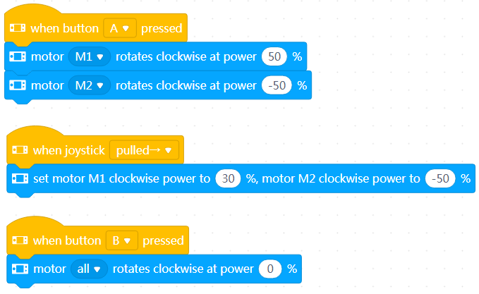
Connect two motors through ports M1 and M2 of the pocket shield.
When you press button A, the output shafts of the two motors rotate; when you move the joystick to the left, the speed of the motor connected M1 changes; and when you press button B, they stop rotating.
Note: You can assemble the two motors on a car robot to drive the wheels before connecting them to CyberPI and then use this example program to control the motion of the car robot. You can control the robot car to turn left or right by setting the power of the two output shafts to different values.
4. motor[fieldMenu_1]rotating power output(%)

Reports the power of the output shaft of the motor connected to the specified port for rotating clockwise
How to use
Click to select a motor from the drop-down list box.
You can select the check box on the left of this block to see the power on the stage.
This is a reporter block that must be used in combination with another block requiring data.
Example
Connect two motors through ports M1 and M2 of the pocket shield.
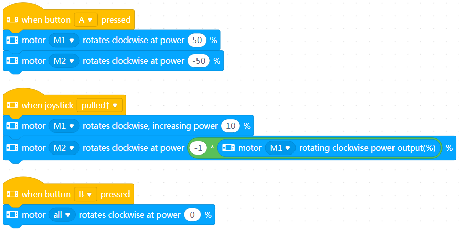
When you press button A, the output shafts of the two motors rotate; when you move the joystick up, the speed of the two motors changes; and when you press button B, they stop rotating.
Note: You can fit the two motors on a car robot to drive the wheels before connecting them to CyberPi and then use this example program to control the motion of the car robot.
5. stop motor [fieldMenu_1]rotating

Stops the rotating of the output shaft(s) of the motor(s) connected to the specified port(s)
How to use
Click to select a motor or both motors from the drop-down list box.
Example
Connect two motors through ports M1 and M2 of the pocket shield.
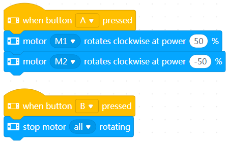
When you press button A, the output shafts of the two motors rotate; and when you press button B, they stop rotating.
Note: You can fit the two motors on a car robot to drive the wheels before connecting them to CyberPi and then use this example program to control the motion of the car robot.
6. set servo[fieldMenu_1]angle to[angle] °
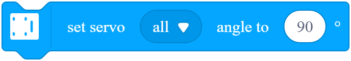
Rotates the servo horn on the servo connected to the specified port to the specified angle
How to use
The pocket shield for CyberPi is equipped with two digital servo ports, S1 and S2, which can be used to connect servos and LED strips.
Click to select a servo or both servos and set the angle.
Setting range of the angle: 0–180 degrees
Example
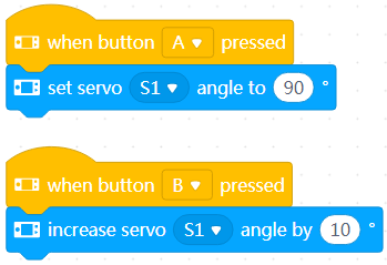
Connect a servo through port S1 of the porcket shield.
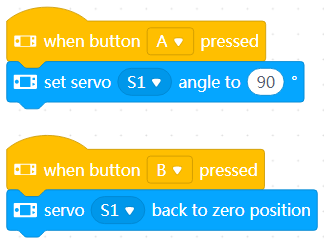
When you press button A, the servo horn on the servo rotates and stops at the position of 90 degrees; and when you press button B, the servo horn rotates and stops at the position of 0 degrees.
7. increase servo[fieldMenu_1]angle by [angle] °
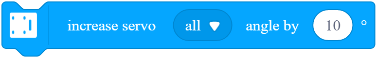
Changes the angle to which the servo horn on the servo connected to the specified port rotates
How to use
The pocket shield for CyberPi is equipped with two digital servo ports, S1 and S2, which can be used to connect servos and LED strips.
Click to select a servo or both servos and set the amount by which the angle is to be changed.
Setting range of the angle: –180 to +180 degrees
A positive value indicates increasing, and a negative one indicates decreasing.
Example
Connect a servo through port S1 of the porcket shield.
When you press button A, the servo horn on the servo rotates and stops at the position of 90 degrees; and when you press button B, the servo horn rotates and stops at the position of 100 degrees.
8. set servo S1 angle to [number_1] ° , servo S2 angle to [number_2] °
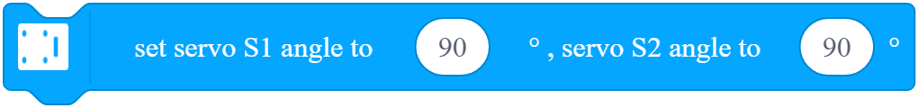
Rotates both the servo horns on the servos connected to the pocket shield to the specified angle
How to use
The pocket shield for CyberPi is equipped with two digital servo ports, S1 and S2, which can be used to connect servos and LED strips.
Click to set the angles.
Setting range of the angle: 0–180 degrees
Example
Connect two servos through ports S1 and S2 of the porcket shield.
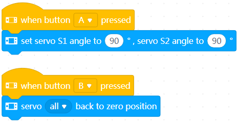
When you press button A, the servo horns on the servos rotate and stop at the position of 90 degrees; and when you press button B, the servo horns rotate and stop at the position of 0 degrees.
9. servo[fieldMenu_1]current angle(°)

Reports the angle to which the servo horn on the servo connected to the specified port rotates
How to use
Click to select a servo from the drop-down list box.
You can select the check box on the left of this block to see the angle on the stage.
This is a reporter block that must be used in combination with another block requiring data.
Example
Connect two servos through ports S1 and S2 of the porcket shield.
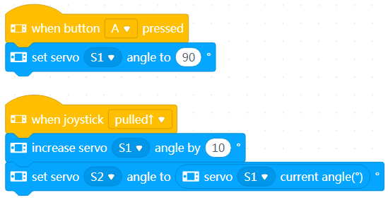
When you press button A, the servo horn on the servo connected to S1 rotates and stops at the position of 90 degrees; and when you move the joystick up, both the servo horns on the servos connected to S1 and S2 rotate and stop at the position of 100 degrees.
10. servo[fieldMenu_1]releases angle
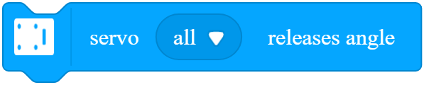
Unlocks the position(s) of the servo horn(s) on the servo(s) connected to the specified port(s)
How to use
After this block is executed for a servo, you can rotate the servo horn on it manually.
Click to select a servo or both servos.
Example
Connect two servos through ports S1 and S2 of the porcket shield.
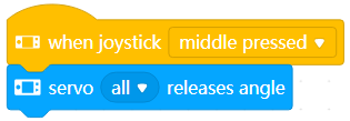
Press the joystick in the middle. The servo horns on the servos are released, and you can rotate them manually.
11. servo[fieldMenu_1]back to zero position

Makes the servo horn(s) on the servo(s) connected to the specified port(s) rotate to the zero-degree position
How to use
Click to select a servo or both servos.
Example
Connect two servos through ports S1 and S2 of the porcket shield.
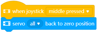
Press the joystick in the middle. The servo horns on the servos rotate to the zero-degree position.
12. LED strip[fieldMenu_1]lights up [facePanel]

Lights up the LED strip(s) connected to the specified port(s) in the specified color(s)
How to use
The pocket shield for CyberPi is equipped with two digital servo ports, S1 and S2, which can be used to connect servos and LED strips.
Click to select an LED strip or both LED strips and set the color(s) for all the LEDs.
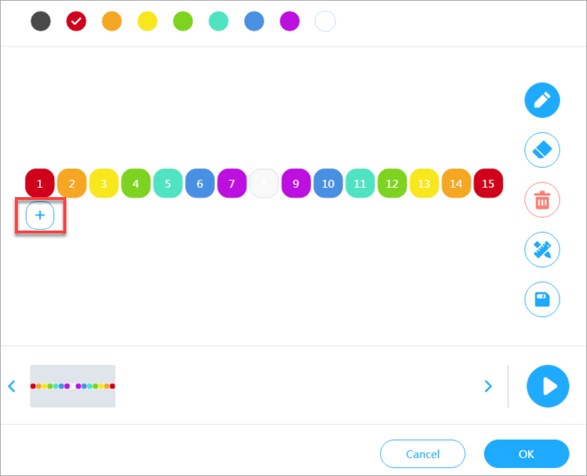
If there are more than 15 LEDs on the LED strip, you can click + to add more LEDs and set their color(s).
Each port can drive a maximum of 36 LEDs, that is, if more than 36 LEDs are set, only the first 36 ones are used.
Example
Connect an LED strip with 30 LEDs on it through port S1 of the porcket shield.
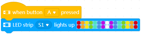
When you press button A, the LEDs on the LED strip are lit up in the specified colors.
13. LED strip[fieldMenu_1]LED[fieldMenu_2]sets color to[color_1]

Lights up the specified LED(s) on the LED strip(s) conneted to the specified port(s) in the specified color
How to use
The pocket shield for CyberPi is equipped with two digital servo ports, S1 and S2, which can be used to connect servos and LED strips.
Click to select an LED strip or both LED strips, select the specified LED, and set the color.
The positions of LEDs on an LED strip are defined as follows.

Starting from the input end (IN), the first LED is numbered 1, the second one is numbered 2, and so on.
Example
Connect an LED strip with 30 LEDs on it through port S1 of the porcket shield.
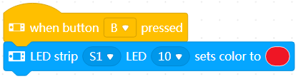
When you press button B, the tenth LED on the LED strip is lit up in red.
14. LED strip[fieldMenu_1] LED[fieldMenu_2]sets color to R: [r] G: [g] B: [b]

Lights up the specified LED(s) on the LED strip(s) conneted to the specified port(s) in the color that is the combination of the specified intensity of red, green, and blue
How to use
The pocket shield for CyberPi is equipped with two digital servo ports, S1 and S2, which can be used to connect servos and LED strips.
Click to select an LED strip or both LED strips, select the specified LED, and set the color.
Color intensity range: 0–255
The positions of LEDs on an LED strip are defined as follows.
Starting from the input end (IN), the first LED is numbered 1, the second one is numbered 2, and so on.
Example
Connect an LED strip with 30 LEDs on it through port S1 of the porcket shield.
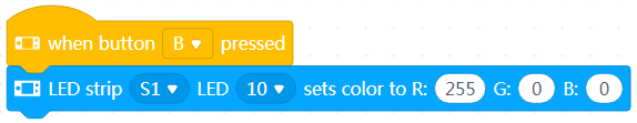
When you press button B, the tenth LED on the LED strip is lit up in red.
15. LED strip[fieldMenu_1]rotates[number_2]LED for[number_3]cycle

Makes the colors of the LEDs on the LED strip(s) connected to the specified port(s) roll from left to right by the specified number of positions in the specified cycle
How to use
Each port can drive a maximum of 36 LEDs.
Setting range of the number of positions by which the LEDs roll: –36 to +36
Setting range of the cycle: 1–36
Example
Connect an LED strip with 30 LEDs on it through port S1 of the porcket shield.
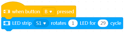
When you press button B, the colors of the LEDs on the LED strip roll from left to right by one position for 29 times, that is, the color in position 1 rolls to postion 30 when the rolling stops.
16. LED strip[fieldMenu_1]LED [fieldMenu_2]lights off

Turns off the specified LED(s) on the LED strip(s) conneted to the specified port(s)
How to use
Click to select an LED strip or both LED strips and select an LED.
Example
Connect an LED strip with 30 LEDs on it through port S1 of the porcket shield.
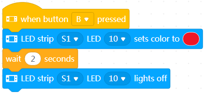
When you press button B, the tenth LED on the LED strip is lit up in red and goes off in 2 seconds.
17. LED strip[fieldMenu_1]increases brightness[number_1]%

Changes the brightness of the LED strip(s) connected to the specified port(s)
How to use
Click to select an LED strip or both LED strips, and set the percentage by which the brightness is to be changed.
Setting range of the change: –100 to +100%
A positive value indicates increasing, and a negative one indicates decreasing.
Example
Connect an LED strip with 30 LEDs on it through port S1 of the porcket shield.
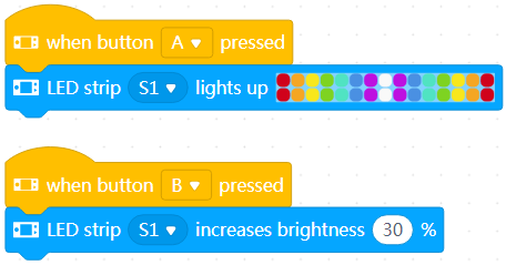
When you press button A, the LEDs on the LED strip are lit up in the specified colors.
When you press button B, the brightness of the LEDs increases.
18. set LED strip[fieldMenu_1]brightness to [number_1] %

Sets the brightness of the LED strip(s) connected to the specified port(s)
How to use
Click to select an LED strip or both LED strips, and set brightness.
Setting range of the brightness: 0–100%
Example
Connect an LED strip with 30 LEDs on it through port S1 of the porcket shield.
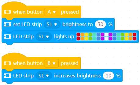
When you press button A, the LEDs on the LED strip are lit up in the specified colors.
When you press button B, the brightness of the LEDs increases.
19. LED strip[fieldMenu_1]brightness(%)

Reports the brightness of the LED strip connected to the specified port
How to use
Click to select an LED strip.
You can select the check box on the left of this block to see the brightness on the stage.
This is a reporter block that must be used in combination with another block requiring data.
Example
Connect an LED strip with 30 LEDs on it through port S1 of the porcket shield.
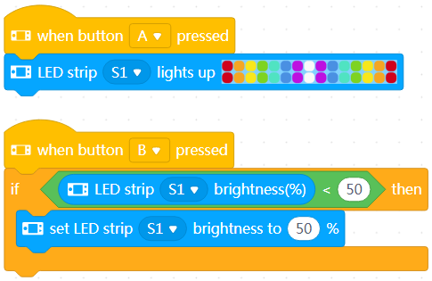
When you press button A, the LEDs on the LED strip are lit up in the specified colors.
After you press button B, if the brightness of the LEDs is lower than 50%, it is set to 50%; and if it is higher or equal to 50%, it stays unchanged.
20. pin[pin_number]on high level?

Determines whether the specified pin is in the high-level state
How to use
Click to select a pin from the drop-down list box.
This is a Boolean block that contains a condition. Use it in combination with another block that requires a condition.
Example
Connect an LED strip with 30 LEDs on it through port S1 of the porcket shield.
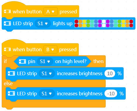
When you press button A, the LEDs on the LED strip are lit up in the specified colors.
When you press button B, the brightness of the LEDs increases or decreases.
21. digital read pin[pin_number]

Reports the digital input of the specified pin
How to use
Click to select a pin.
Digital input range: 0 or 1
0: low level; 1: high level
You can select the check box on the left of this block to see the digital input of the pin on the stage.
This is a reporter block that must be used in combination with another block requiring data.
Example
Connect an LED strip with 30 LEDs on it through port S1 of the porcket shield.
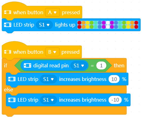
When you press button A, the LEDs on the LED strip are lit up in the specified colors.
When you press button B, the brightness of the LEDs increases or decreases.
22. read pin [inputMenu_1]voltage(V)

Reports the voltage of the specified pin
How to use
Click to select a pin.
Voltage value range: 0–5 V
You can select the check box on the left of this block to see the voltage of the pin on the stage.
This is a reporter block that must be used in combination with another block requiring data.
Example
Connect an LED strip with 30 LEDs on it through port S1 of the porcket shield.
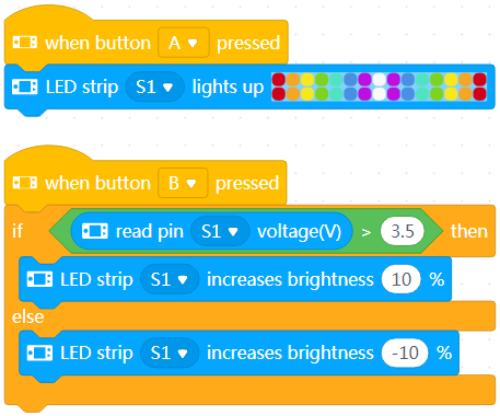
When you press button A, the LEDs on the LED strip are lit up in the specified colors.
When you press button B, the brightness of the LEDs increases or decreases.
23. write pin[fieldMenu_1]digital value[Digtial_value]

Sets the specified digital input for the specified pin(s)
How to use
Click to select a pin or both ports and set the digital input.
Setting range of the digital input: 0 or 1; any non-zero value is processed as 1
Example
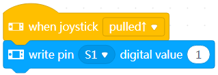
Move the joystick up. The digital input of the pin is set to 1.
24. write pin[pin_number]PWM, duty cycle[PWM_value]%, frequency[fieldMenu_3]Hz

Sets the specified pin(s) to output PWM signals with the specified duty cycle and frequency
How to use
What is PWM?
Pulse-width modulation (PWM) is technology for performing digital encoding on analog signals. It involves two key parameters, namely frequency and duty cycle. The frequency determines the time required for completing a single cycle and the rate at which signals change from high to low level. The duty cycle determines the time the signals stay in high level within the total period of time. By changing the duty cycle of PWM, you can change the average voltage of the output signals, and thus provide analog voltage output.
Click to select a pin or both pins from the drop-down list box and set the duty cycle and frequency.
Setting range of the duty cycle: 0–100%
Setting range of the frequency: 1–2000 Hz
Example
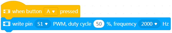
When you press button A, the pin outputs PWM signals with the duty cycle of 50% and frequency of 2000 Hz.