How Can We Help?
mBot2 Extension Port
15. motor [fieldMenu_1] rotates at [number_2]% power

Provides the specified power at the specified motor port
How to use
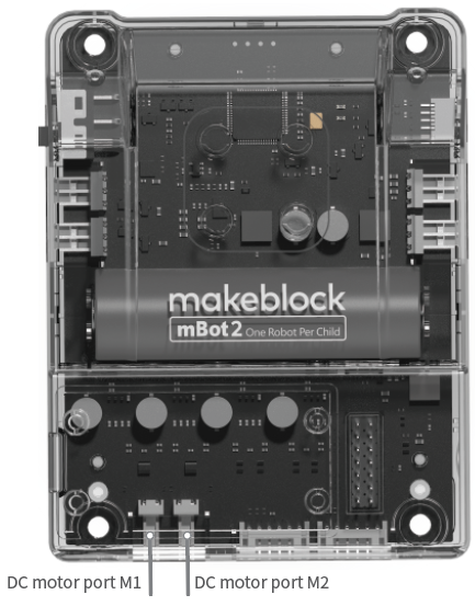
mBot2 provides two DC motor ports, M1 and M2.
Setting range of the power: –100 to +100 (%)
When you set the power to a positive value, the output shaft of the motor rotates counterclockwise; and when you set it to a negative one, the output shaft of the motor rotates clockwise.
Click to select a motor port or both the motor ports.
Example
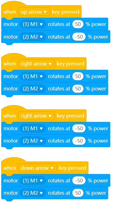
Use two DC motors and wheels to build a movable structure, connect the left motor to port M1, and connect the right motor to port M2.
When you press the up arrow key, the structure moves forward; when you press the right arrow key, it turns right; when you press the left arrow key, it turns left; and when you press the down arrow key, it moves backward.
16. motor [fieldMenu_1] rotates with power up [power]%

Increases the power at the specified port by the specified amount
How to use
Click to select a motor port or both the motor ports from the drop-down list box and set the amount by which the power is to be increased.
Setting range of the power: –200 to +200 (%)
Example
Use two DC motors and wheels to build a movable structure, connect the left motor to port M1, and connect the right motor to port M2.
When you press the space key, the structure moves forward; and when you press the up arrow key, the structure accelerates forward.
17. set motor M1 power to [number_1]% , motor M2 power to [number_2]%

Provides the specified power at the two motor ports
How to use
Click to set the power at each motor port.
Setting range of the power: –100 to +100 (%)
Example
Use two DC motors and wheels to build a movable structure, connect the left motor to port M1, and connect the right motor to port M2.
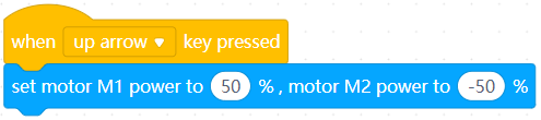
When you press the up arrow key, the structure moves forward.
18. motor [fieldMenu_1] rotation output power(%)

Reports the output power of the specified motor port
How to use
Click to select a motor port from the drop-down list box.
Value range of the power: –100 to +100 (%)
Note: This is a reporter block that must be used in combination with another block requiring data.
Example
Use two DC motors and wheels to build a movable structure, connect the left motor to port M1, and connect the right motor to port M2.
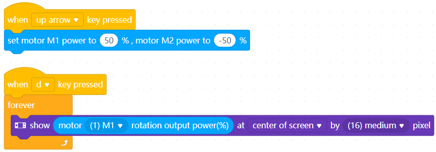
When you press the up arrow key, the structure moves forward; and when you press the d key, the display on CyberPi displays the output power of motor port M1 in real time.
19. stop motor [fieldMenu_1]

Stops the power output of the specified motor port
How to use
Click to select a motor port or both the motor ports from the drop-down list box.
Example
Use two DC motors and wheels to build a movable structure, connect the left motor to port M1, and connect the right motor to port M2.
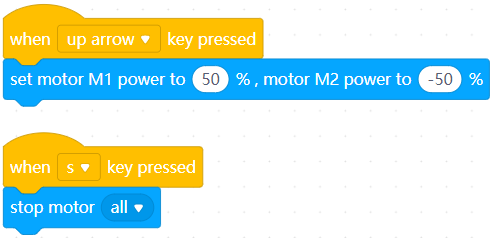
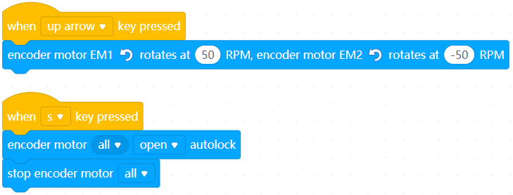
When you press the up arrow key, the structure moves forward; and when you press the s key, the structure stops moving.
20. set servo [fieldMenu_1] angle to [angle]°

Rotates the output shaft(s) of the servo(s) connected to the specified port(s) to the specified number of degrees
How to use
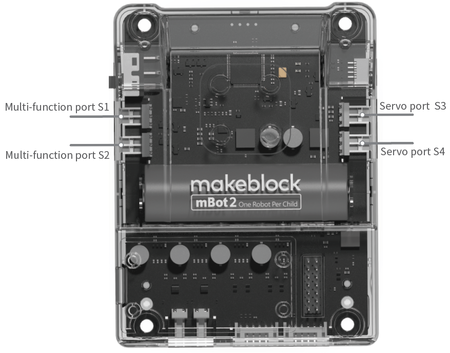
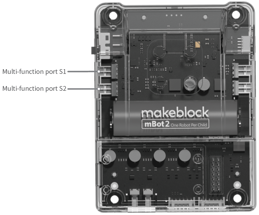
mBot2 provides two multi-function ports and two servo ports, and the multi-function ports can serve as servo ports.
Click to select a port from the drop-down list box and set the number of degrees.
Setting range of the degrees: 0–180 (degrees)
Example
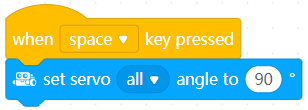
When you press the space key, all the output shafts of the servos connected to mBot2 rotate to the position of 90 degrees.
21. increase servo [fieldMenu_1] angle by [angle]°
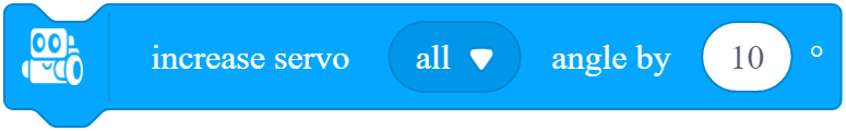
Changes the number of degrees the output shaft(s) of the servo(s) connected to the specified port(s) rotates by the specified amount
How to use
If you haven’t set the degrees of the output shaft of a servo, when this block is executed, the output shaft rotates to the position of 20 degrees by default before rotating the added degrees.
Click to select a port or all the ports from the drop-down list box and set the number of degrees.
Setting range of the degrees: –180 to +180 (degrees)
Example
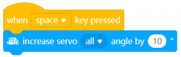
When you press the space key, all the output shafts of the servos connected to mBot2 rotate 10 degrees from the original positions.
22. set servo angle S1 [number_1]° , S2 [number_2]° , S3 [number_3]°, S4 [number_4]°
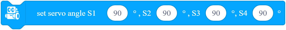
Rotates the output shafts of the servos to the specified number of degrees separately
How to use
Click to set the number of degrees for the output shaft of the servo connected to each servo port.
Setting range of the degrees: 0–180 (degrees)
Example
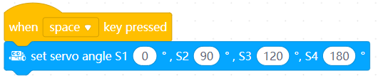
When you press the space key, the output shafts of the servos connected to mBot2 rotate to the specified positions separately.
23. servo [fieldMenu_1] current angle (°)

Reports the number of degrees of the position to which the output shaft of the servo connected to the specified port rotates
How to use
Click to select a port from the drop-down list box.
This is a reporter block that must be used in combination with another block requiring data.
Example
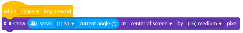
When you press the space key, the display on CyberPi displays the degrees of the position to which the output shaft of the servo connected to port S1 rotates.
24. servo [fieldMenu_1] release angle

Releases the output shaft(s) of the servo(s) connected to the specified port(s)
How to use
Click to select a port or all the ports from the drop-down list box.
After the output shaft of a servo is released, you can manually rotate the output shaft of the servo.
Example
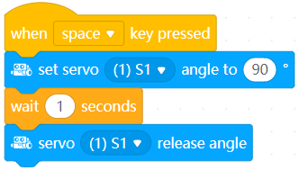
After you press the space key, the output shaft of the servo connected to port S1 rotates to the position of 90 degrees, and you can manually rotate the output shaft in one second.
25. servo [fieldMenu_1] back to zero position

Rotates the output shaft(s) of the servo(s) connected to the specified port(s) to the zero-degree position
How to use
Click to select a port or all the ports from the drop-down list box.
Example
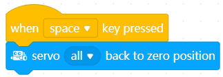
When you press the space key, the output shafts of all the servos connected to mBot2 rotate to the zero-degree position.
26. LED strip [fieldMenu_1] lights up [facePanel]

Lights up the LEDs on the LED strip connected to the specified port in the specified color(s)
How to use
mBot2 provides two multi-function ports, S1 and S2, that can drive LED strips, supporting a maximum of 36 LEDs.
If you set color(s) for more than 36 LEDs, only the colors of the first 36 LEDs take effect.
Click to select a port or all the ports from the drop-down list box, and click to set the color(s) of the LEDs.
Example
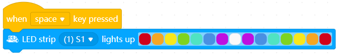
When you press the space key, the LED strip connected to port S1 is lit up in the specified colors.
27. LED strip [fieldMenu_1] LED [fieldMenu_2] displays color [color_1]

Lights up the specified LED(s) on the LED strip(s) connected to the specified port(s) in the specified color
How to use
Click to select a port or all the ports and select an LED or all the LEDs from the drop-down list boxes, and click to set the color.
Example
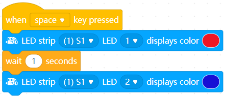
When you press the space key, the first LED on the LED strip connected to port S1 is lit up in red, and the second LED is lit up in blue in one second.
28. LED strip [fieldMenu_1] LED [fieldMenu_2] displays R: [r] G: [g] B: [b]

Lights up the specified LED(s) on the LED strip(s) connected to the specified port(s) in the color that is the combination of the specified intensity of red, green, and blue
How to use
Click to select a port or all the ports and select an LED or all the LEDs from the drop-down list boxes, and click to set the color value.
R: red
G: green
B: blue
Setting range of the color values: 0–255
Example
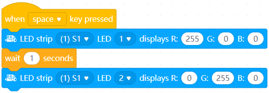
When you press the space key, the first LED on the LED strip connected to port S1 is lit up in red, and the second LED is lit up in green in one second.
29. LED strip [fieldMenu_1] rolls [number_2] LEDs with cycle [number_3]

Makes the colors of the LEDs on the LED strip connected to the specified port roll from left to right by the specified number of positions for the specified number of times
How to use
Click to select a port or all the ports from the drop-down list box and set the number of positions and times.
Example
A 12-LED strip is used.
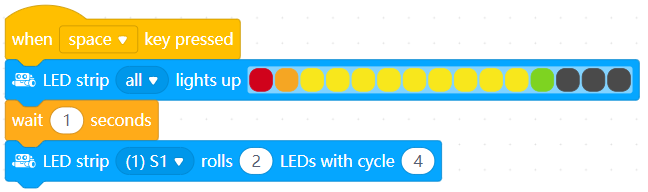
When you press the space key, the LED strip is lit up as follows.

The colors of the LEDs roll from left to right as follows in one second.

30. LED strip [fieldMenu_1] LED [fieldMenu_2] lights off

Turns off the specified LED(s) on the LED strip(s) connected to the specified port(s)
How to use
Click to select a port or all the ports and select an LED or all the LEDs from the drop-down list box.
Example
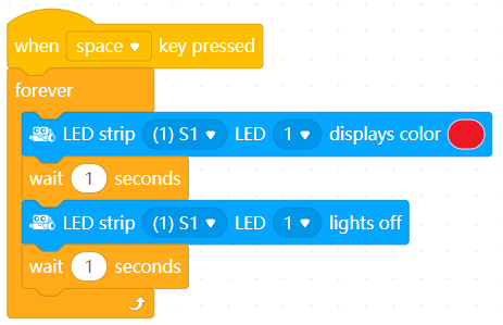
After you press the space key, the first LED on the LED strip connected to port S1 is turned on and off alternately.
31. increase LED strip [fieldMenu_1] brightness by [number_1] %

Changes the brightness of the LED strip connected to the specified port
How to use
Click to select a port or all the ports from the drop-down list box, and set the amount by which the brightness is to be changed.
Setting range of the amount:–100 to +100 (%)
A positive value indicates that the brightness is to be increased, and a negative one indicates that the brightness is to be reduced.
Example
A 12-LED strip is used.
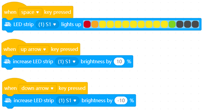
When you press the space key, the LED strip connected to port S1 is lit up in the specified colors. Then, you can press the up and down arrow keys to change the brightness of the LED strip.
32. set LED strip [fieldMenu_1] brightness to [number_1]%

Sets the brightness of the LED strip connected to the specified port
How to use
Click to select a port or all the ports from the drop-down list box and set the brightness.
Setting range of the brightness: 0–100 (%)
Example
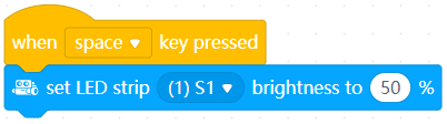
When you press the space key, the brightness of the LED strip connected to port S1 is set to 50%.
33. LED strip [fieldMenu_1] brightness(%)

Reports the brightness of the LED strip connected to the specified port
How to use
Click to select a port from the drop-down list box.
This is a reporter block that must be used in combination with another block requiring data.
Example
A 12-LED strip is used.
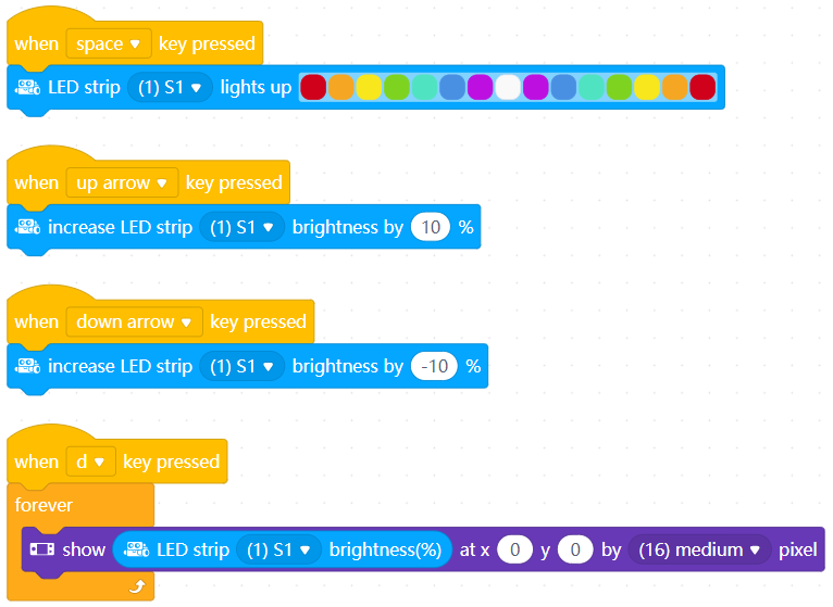
When you press the space key, the LED strip connected to port S1 is lit up in the specified colors. Then, you can press the up and down arrow keys to change the brightness of the LED strip. After you press the d key, you can see the brightness of the LED strip on the display of CyberPi in real time.
34. pin [pin_number] on high level?

Determines whether the specified pin is in the high-level state
How to use
Click to select a pin from the drop-down list box.
This is a Boolean block that contains a condition. Use it in combination with another block that requires a condition.
Example
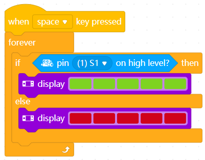
After you press the space key, the LEDs on CyberPi are lit up in green if pin S1 is in the high-level state and in red if it is in the low-level state.
35. digital read pin [pin_number]

Reports the digital input of the specified pin
How to use
Click to select a pin.
Digital input range: 0 or 1
0: low level; 1: high level
This is a reporter block that must be used in combination with another block requiring data.
Example
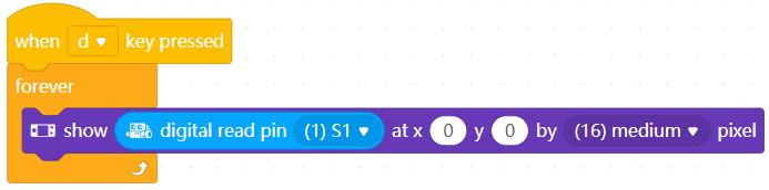
After you press the d key, you can view the digital input of pin S1 on the display of CyberPi in real time.
36. voltage read pin [inputMenu_1](V)

Reports the voltage at the specified pin
How to use
Click to select a pin.
Voltage value range: 0–5 V
This is a reporter block that must be used in combination with another block requiring data.
Example
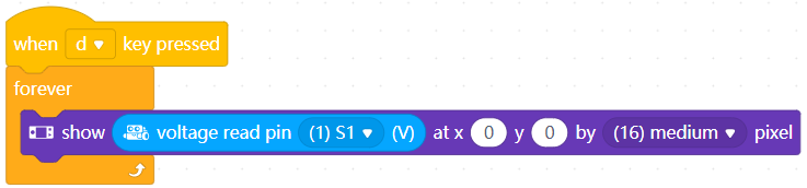
After you press the d key, you can view the voltage at pin S1 on the display of CyberPi in real time.
37. digital write [Digtial_value] to pin [fieldMenu_1]

Sets the specified digital input for the specified pin(s)
How to use
Click to select a pin or both ports and set the digital input.
Setting range of the digital input: 0 or 1; any non-zero value is processed as 1
Example
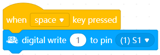
When you press the space key, the digital input of pin S1 is set to 1.
38. analog write to pin[pin_number], duty cycle[PWM_value]%, frequency [fieldMenu_3]Hz

Sets the specified pin(s) to output PWM signals with the specified duty cycle and frequency
How to use
What is PWM?
Pulse-width modulation (PWM) is technology for performing digital encoding on analog signals. It involves two key parameters, namely frequency and duty cycle. The frequency determines the time required for completing a single cycle and the rate at which signals change from high to low level. The duty cycle determines the time the signals stay in high level within the total period of time. By changing the duty cycle of PWM, you can change the average voltage of the output signals, and thus provide analog voltage output.
Click to select a pin or both pins from the drop-down list box and set the duty cycle and frequency.
Setting range of the duty cycle: 0–100%
Setting range of the frequency: 1–2000 Hz
Example
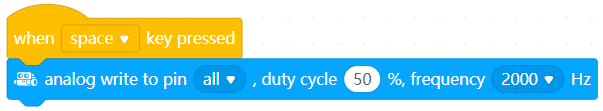
When you press the space key, all the pins output PWM signals with the duty cycle of 50% and frequency of 2000 Hz.