How Can We Help?
Use Laserbox Software
Project management
The software Laserbox manages files in the form of projects. Project management includes creating New Project and opening Recent Open.
New project
New Project is the first interface that you’ll see after you opened the software. You can create a brand-new project or directly import a project offered by Makeblock.
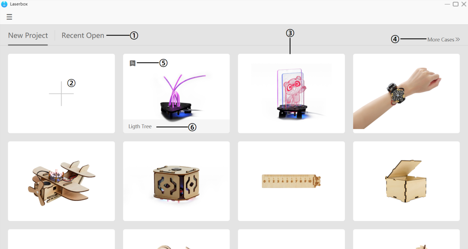
- Recent Open Click on it to switch to the interface you can find the projects you recently opened.
- Add a new project Click it to create a brand-new project.
- Sample projects Click sample projects to see in-built examples.
- More Cases Click it to redirect to Makeblock Education where you could find more Laserbox projects.
- Details Click this button to redirect to Makeblock Education where you can access project-related descriptions, assembling video and more resources.
- Project name Here displays the project name.
Recent open
In this interface, you can find the projects you recently opened or edited in Laserbox. Laserbox automatically saves your project when you exit the project.
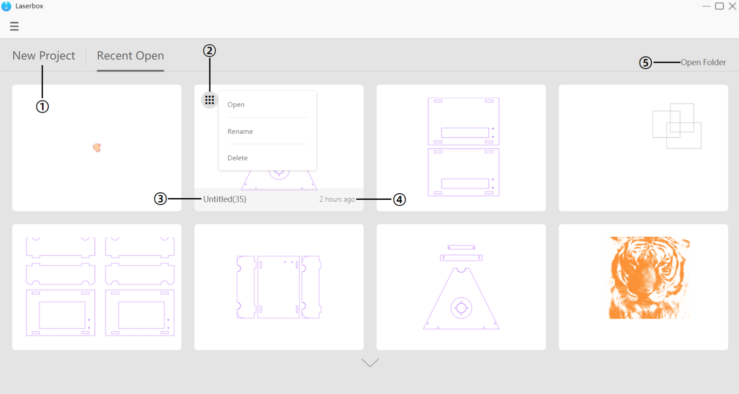
- New Project Click it to switch to the New Project interface.
- Operate Click it to open, rename or delete the project.
- Project Name Here displays the project name.
- Project Time Here displays the time when the recent project was saved.
- Open Folder Open the folder into which Laserbox automatically saves projects.
Interface tour
Working interface
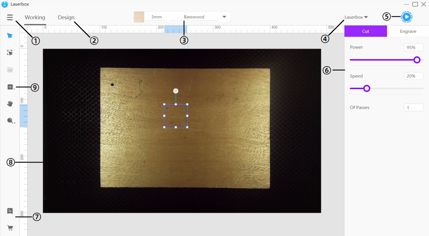
- Menu In Menu, you can import/export files, or change settings.
- Working/Design Click it to switch between interfaces.
- Material management Here displays the material already identified or set up. Click to select a material for processing, add a new material or change the processing parameters.
- Device management Here displays the connected device. Click it to manage all the devices that were once connected.
- Start button Click the start button to start a cutting or engraving procedure.
- Parameter settings panel Use this panel to change cutting or engraving parameters. Parameters are displayed only when there’s a layer on the canvas. If you enable Show Color Block in Settings, then the panel will display custom parameters.
- Other links Visit Makeblock official website or online store to access more courses or buy consumables.
- Canvas The canvas is the area where you create images for processing. It’s the same as the working area in the laser cutter. So when the software is connected to the laser cutter, the canvas will display the picture from the camera in real time.
- Toolbar The toolbar includes many tools and options that are frequently used.
Design interface
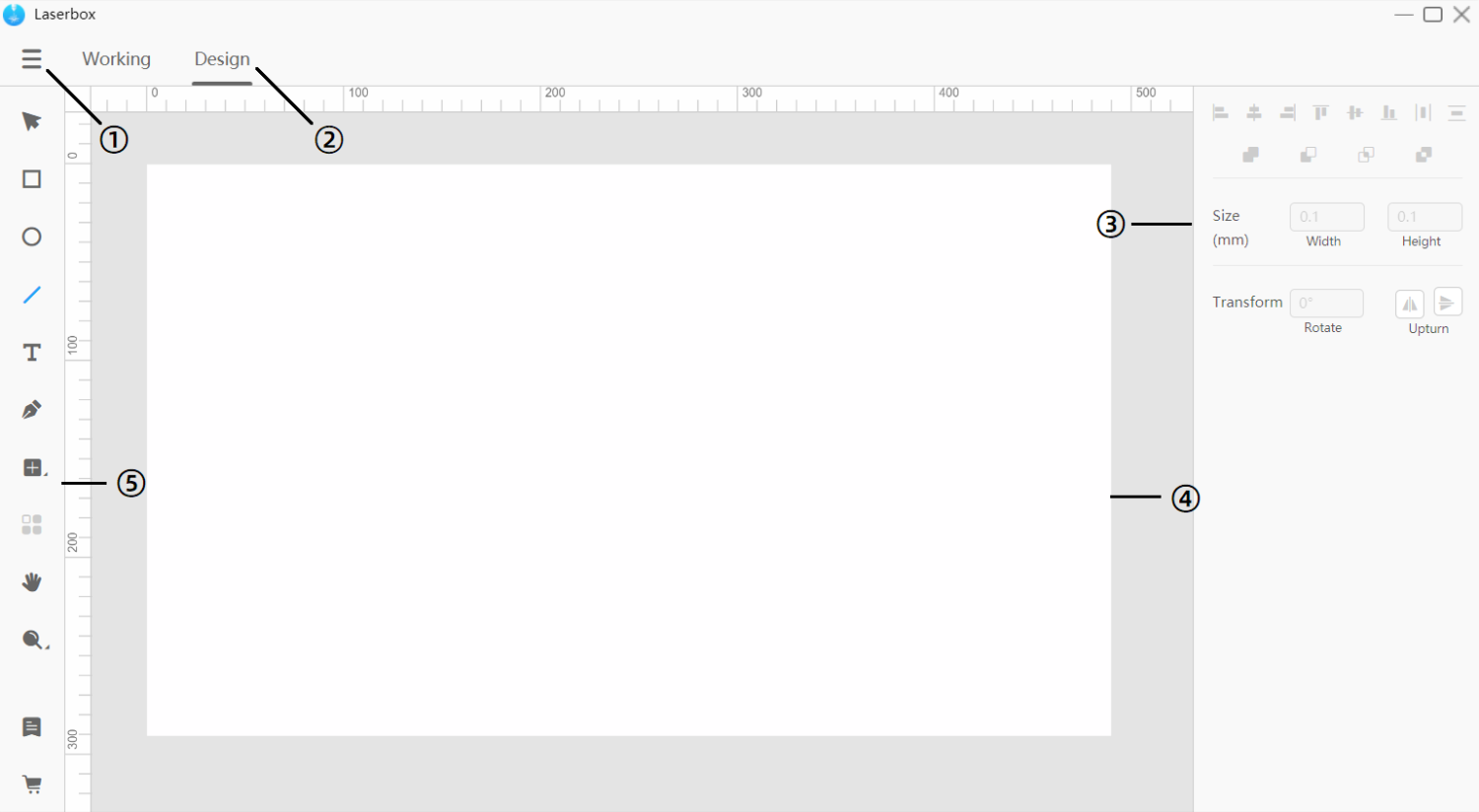
- Menu In Menu, you can import/export files, or change settings.
- Working/Design Click to switch between interfaces.
- Styles panel This panel includes lots of tools allowing you to combine and change shapes to create more complex images.
- Canvas The canvas is the area where you design and edit images for processing.
- Toolbar The toolbar includes many tools and options that are frequently used.
Canvas
Both the working interface and design interface have a canvas. They have the same features, except that you can set up the canvas in the working interface to display images from the camera in real time.
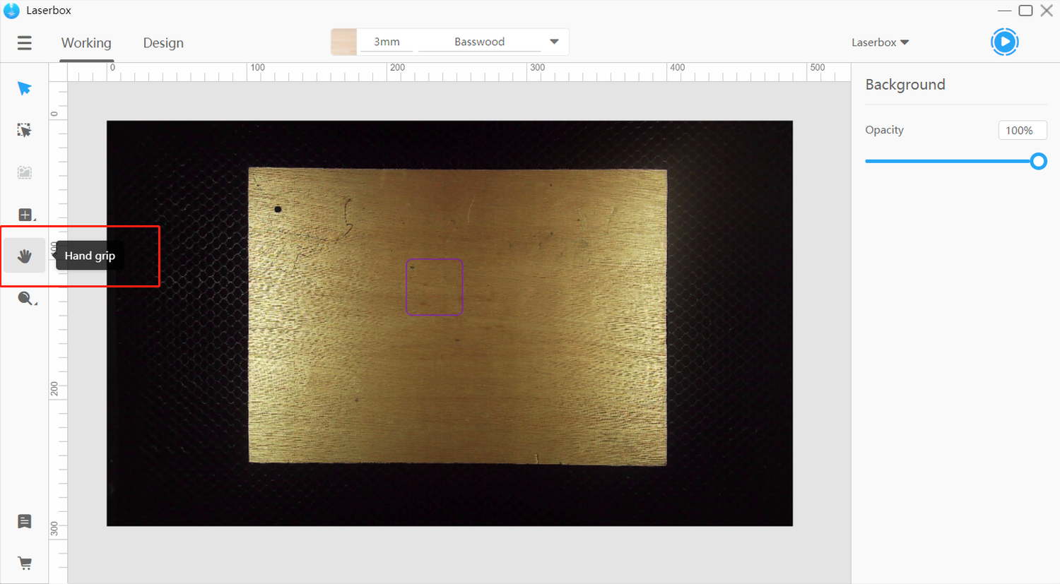
Drag canvas
On the left toolbar, click on Hand grip. Then, hold down the left mouse button to drag the canvas. Or, you can hold down the space key and left click the mouse to drag the canvas.
Zoom in/out
In the left toolbar, click the Zoom button – the magnifier icon, then you can change the canvas size on the pop-up list. You can also scroll the mouse wheel to adjust the canvas size.
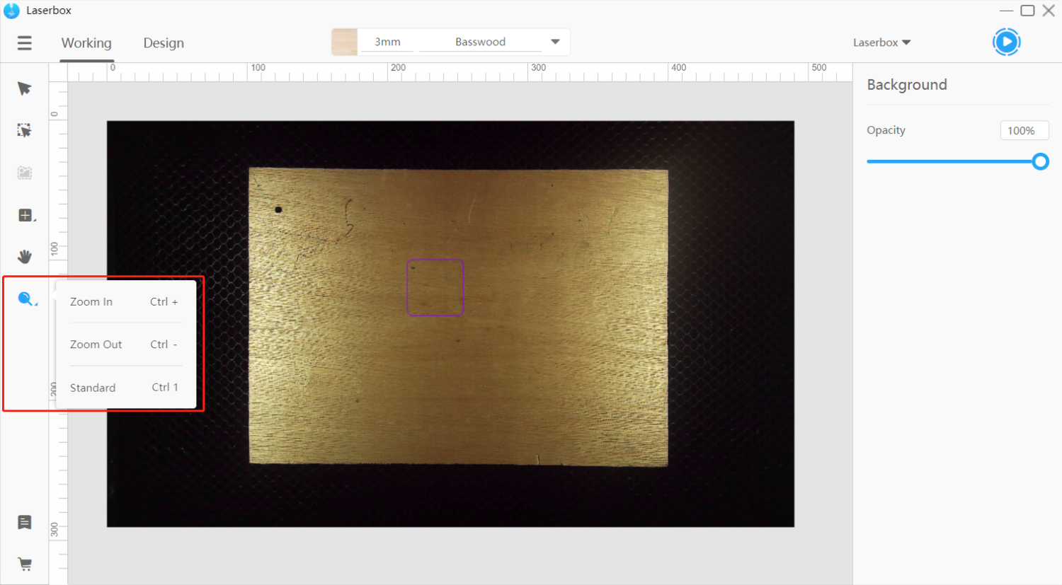
- Zoom in Make the canvas appear bigger.
- Zoom out Make the canvas appear smaller.
- Standard Make the canvas fit the current window size.
Auto align and distance measurement
When you drag one of the layers, alignment lines will be generated so that you can easily align this layer with the edges or center of another layer. Meanwhile, the distance between two layers will be displayed.
This feature also applies to the situation where you drag the corners of a layer to resize it. It helps you keep two layers at the same height or width.
Menu
In Menu, you can do plenty of things. The working interface and design interface have the same menu list.
- Import Import projects or image files into the canvas. The shortcut is [Ctrl] + [O]. Or you can directly drag a file into the canvas.
- Export Save the file as lq format specific to Laserbox. The shortcut is [Ctrl] + [E].
- Back to files Back to the project management interface.
- Edit Edit layers.
- View Zoom in /out or drag the canvas.
- Settings Change the settings for the software and laser cutter that’s connected.
- Help Redirect to websites where you can see help documents.
- Exit Close the software.
Toolbar
The working interface and design interface have different toolbars.
3.1 Toolbar in working interface
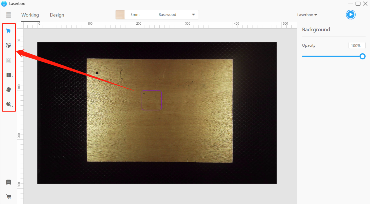
- Select Left click or frame a layer to select it.
- Marquee Extract images from the camera on the laser cutter. Learn more about Extract Images.
- Outline Extract outlines from the images on the canvas. Learn more about Extract Outlines.
- Insert Insert in-built graphs or components. Learn more about Insert Elements.
- Hand grip Drag the canvas to see different parts of the canvas.
- Zoom Make the canvas appear larger or smaller.
3.2 Toolbar in design interface
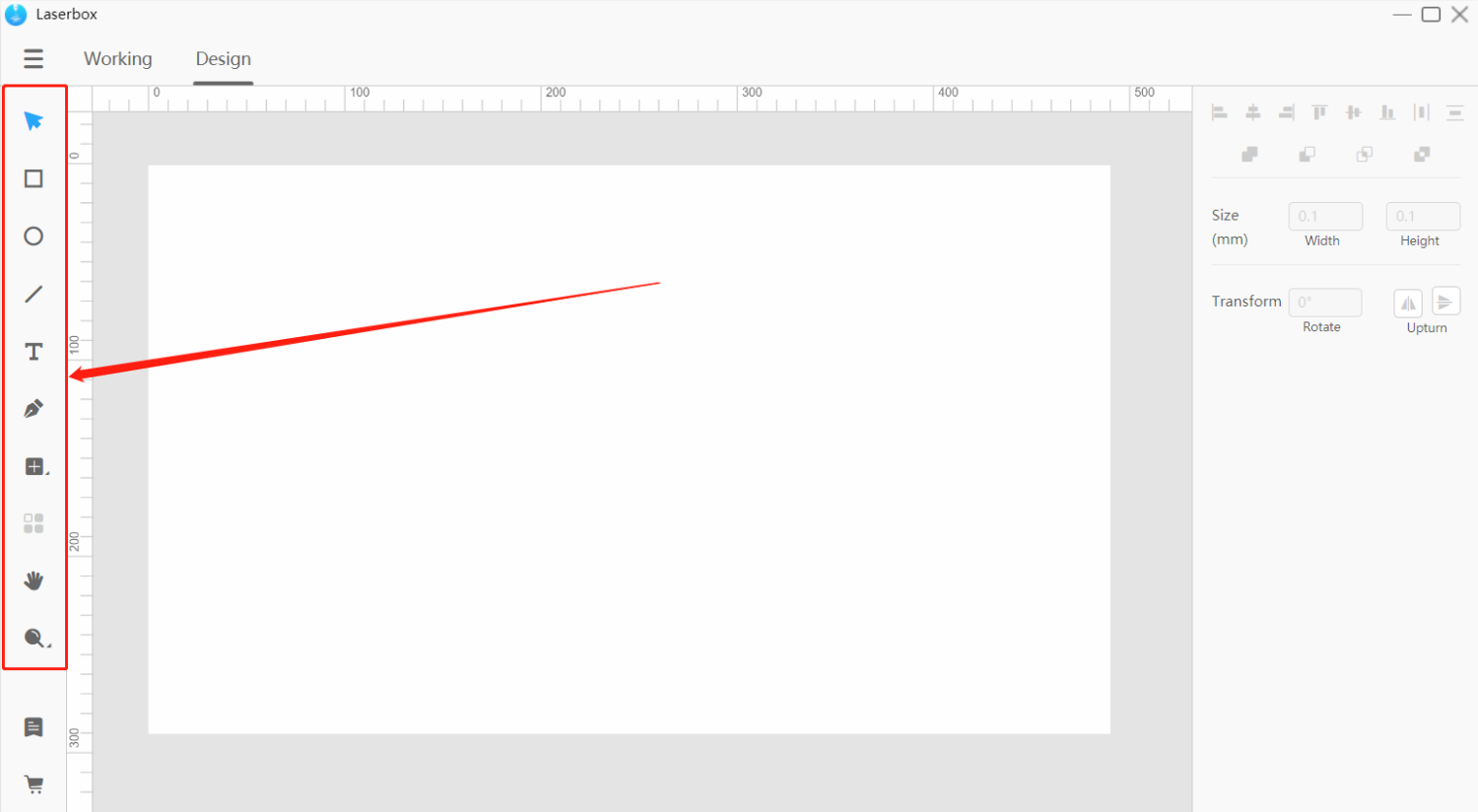
- Select Left click or frame a layer to select it.
- Rectangle Create rectangle layers in the canvas.
- Oval Create oval layers in the canvas.
- Line Create line layers in the canvas.
- Text Create texts in the canvas.
- Pen Create vector paths in the canvas.
- Insert Insert in-built graphs or components. Learn more about Insert Elements.
- Array Quickly duplicate layers and arrange them in the way you set up.
- Hand grip Drag the canvas to see different parts of the canvas.
- Zoom Make the canvas appear larger or smaller.
Add layers
Layers are a collection of elements such as vectors, bitmaps, texts, lines and more. Laserbox allows users to make adjustments on every single layer so you can change the engraving power and speed for each layer in order to create different effects. In the software Laserbox, the first layer you create is at the bottom, and the final layer you create is at the top.
Laserbox supports importing vectors and bitmaps. You can engrave or cut vectors, but you can only engrave bitmaps.
Add layers in the working interface
Import images
Go to Menu > Import, then select the image file you’d like to import. Or, you can directly drag an image into the canvas. The shortcut is [Ctrl] + [O].
Extract images
The Marquee tool enables you to extract images from the camera on the laser cutter. Click on Marquee in the toolbar to frame any portion you’d like to extract. Learn more about Extract Images.
Extract outlines
The Outline tool automatically outlines a bitmap. The result can be used for the laser cutter to cut the image by its outline. Select a bitmap layer made of enclosed outlines, then click on Outline in the toolbar, and wait until a vector path layer of the outline is generated. Set up in the software to cut the enclosed outline. Learn more about Extract Outlines.
Insert
The Insert tool contains the options you can use to draw shapes on the canvas. Click Insert on the toolbar on the left, and select graphs or components on the panel. Click and drag the shape or part into the canvas to insert it.
Add layers in the Design interface.
Rectangle
For making rectangles. In the Design interface, select Rectangle on the toolbar on the left, and then drag on the canvas to create a rectangle. If you hold down Shift while dragging the mouse, you lock the width-height ratio to 1:1, which means you’re drawing a square. The keyboard shortcut to draw a rectangle is [R].
When you draw a rectangle, its width and height appear at the bottom right corner of the mouse-pointer.

Oval
Used to draw an ellipse. In the Design interface, select Oval on the toolbar, and then drag on the canvas to make an ellipse. You can draw a perfect circle by holding down Shift when you drag the mouse. Doing this will lock the aspect ratio to 1:1. The keyboard shortcut to create an ellipse is [O].

Line
For drawing lines. In the Design interface, select Line on the toolbar and drag on the canvas. Then a line will be created between the location where you click the mouse and where you release the mouse button. The keyboard shortcut to insert a line is [L].

Text
Used to insert text. In the Design interface, click Text on the toolbar, and then drag on any blank space on the canvas to insert a text box. When the insertion point appears inside the text box, it means you can type to create text. Click on any blank space to exit text editing. The keyboard shortcut to insert text is [T].
Pen
For creating paths on the canvas as you like. In the Design interface, click Pen on the toolbar, and click on the blank space on the canvas to insert an anchor point. The tool creates vector paths between anchor points. To ensure a smooth curve at an anchor point, drag your mouse when inserting the anchor point. Move your mouse to control the direction of the path. To close the path, click on the first anchor point you set down. Press Esc on your keyboard to exit pen drawing and create an open path.The keyboard shortcut to insert text is [P].

Array
For creating copies of layers and arranging them. Select a layer on the canvas, click Array on the toolbar in the Design interface, and specify how many rows and columns you want and the spacing between the copies.
Basic tools
Edit
Go to Menu > Edit. Keyboard shortcuts:
| Action | Keyboard shortcuts |
| Action | [Ctrl] + [Z] |
| Undo | [Ctrl] + [Y] |
| Redo | [Ctrl] + [X] |
| Cut | [Ctrl] + [C] |
| Copy | [Ctrl] + [V] |
| Paste | [Delete] |
| Delete | [Ctrl] + [A] |
- Undo Reverses your last action. Go to Menu > Edit > Undo to remove the last change you’ve done to the canvas. You can also press [Ctrl] + [Z] on your keyboard to undo actions.
- Redo Reverses something you’ve undone. To redo your last undo, go to Menu > Edit > Redo. The Redo button is grey and unavailable until you undo an action. The keyboard shortcut to redo something is [Ctrl] + [Y].
- Cut Right-click a layer and select Cut to add it to the clipboard. The layer then disappears on the canvas. The keyboard shortcut to cut a layer is [Ctrl] + [X].
- Copy Right-click a layer and select Copy to add it to the clipboard. The layer remains on the canvas when you do this. You can also press [Ctrl] + [C] to quickly copy a layer.
- Paste Right-click anywhere on the canvas and select Paste to insert the copied layer from the clipboard. The keyboard shortcut to paste a copied layer is [Ctrl] + [V].
- Delete Right-click a layer and select Delete to remove it from the canvas. The keyboard shortcut for this action is [Delete].。
- Select All Right-click any blank space and click Select All to select all contents on the canvas. The keyboard shortcut is [Ctrl] + [A].
Style tools
Size
When you select a layer, anchor points appear on its borders. Drag the anchor points to resize the layer. Or, you can specify the width and height in the style panel on the right for more accurate size control.
Click the lock icon between the size parameters to lock/unlock the aspect ratio. If the aspect ratio is locked, it won’t change even when you drag the anchor points of the layer or adjust the size parameters. If the ratio isn’t locked, you can adjust the width or height without changing the other. To quickly lock the aspect ratio, hold down Shift when dragging the anchor points of a layer.
Transform
- Rotate When you select a layer, a rotation handle appears at the top of it. Drag the handle to rotate the layer or specify the rotation angle in the style panel.
- Upturn Click Upturn to flip the layer horizontally or vertically.
Fills
When you select a closed vector image or text, the Fills option appears on the style panel. Tick Fills to color the closed shape or text.
Crop
When you select an image, you can crop it. Right-click on the image, select Crop, and adjust the crop box. Then click on blank space. The part in the crop box remains on the canvas and the part outside the box will be removed. You can also double-click on the image to crop it quickly.
Filter setting
When you select an image, the Filter Setting appears in the style panel. Click the options to apply different filters to your image. To remove an applied filter, click the filter again.
Edit text
When you select a text, the text editing options appear in the style panel. Click the text again to start editing it.
- Typeface Changes the font of your text.
- Space Changes the spacing between words and lines.
Line style
When you select a line, the line style options appear in the panel. Click the drop-down list to change styles.
Pen tool anchor points
When you select a vector path that is created with the pen tool, you can double-click the layer to edit the anchor points. Select an anchor point and define it as a Corner Point or Smooth Point in the style panel on the right.
Alignment tools
When you select more than one layer, you can align them with the alignment tools. The alignment options include:
NOTE: Distribute Horizontally and Distribute Vertically are only available when you select three or more layers.
- Align Left Aligns the left edges of the selected layers to the left edge of the leftmost layer, or to the left edge of the selection box.
- Align Center Aligns the vertical center of each selected layer to the vertical center of the selection box.

- Align Right Aligns the right edges of the selected layers to the right edge of the rightmost layer, or to the right edge of the selection box.

- Align Top Aligns the top edges of the selected layers to the topmost edge of all selected layers, or to the top edge of the selection box.
- Align Middle Aligns the horizontal center of each selected layer to the horizontal center of the selection box.

- Align Bottom Aligns the bottom edges of the selected layers to the bottommost edge of all layers, or to the bottom edge of the selection box.

- Distribute Horizontally Distributes the horizontal spacing between the selected layers evenly.

- Distribute Vertically Distributes the vertical spacing between the selected layers evenly.

Boolean operations
Use Boolean operations to transform two or more shapes into one. Four types of operations are available:
- Union Merges multiple shapes into one.

- Subtraction Removes the region of the bottom shape that is covered by the top shape and keeps the uncovered region of the bottom shape.
- Intersection Keeps the overlapping region and deletes the rest of the shapes. If the shapes aren’t overlapping at all, then all shapes will be removed.
- Differentiation Removes the overlapping region of the shapes and leaves the rest on the canvas. Opposite to Intersection.

Materials management
Select a material
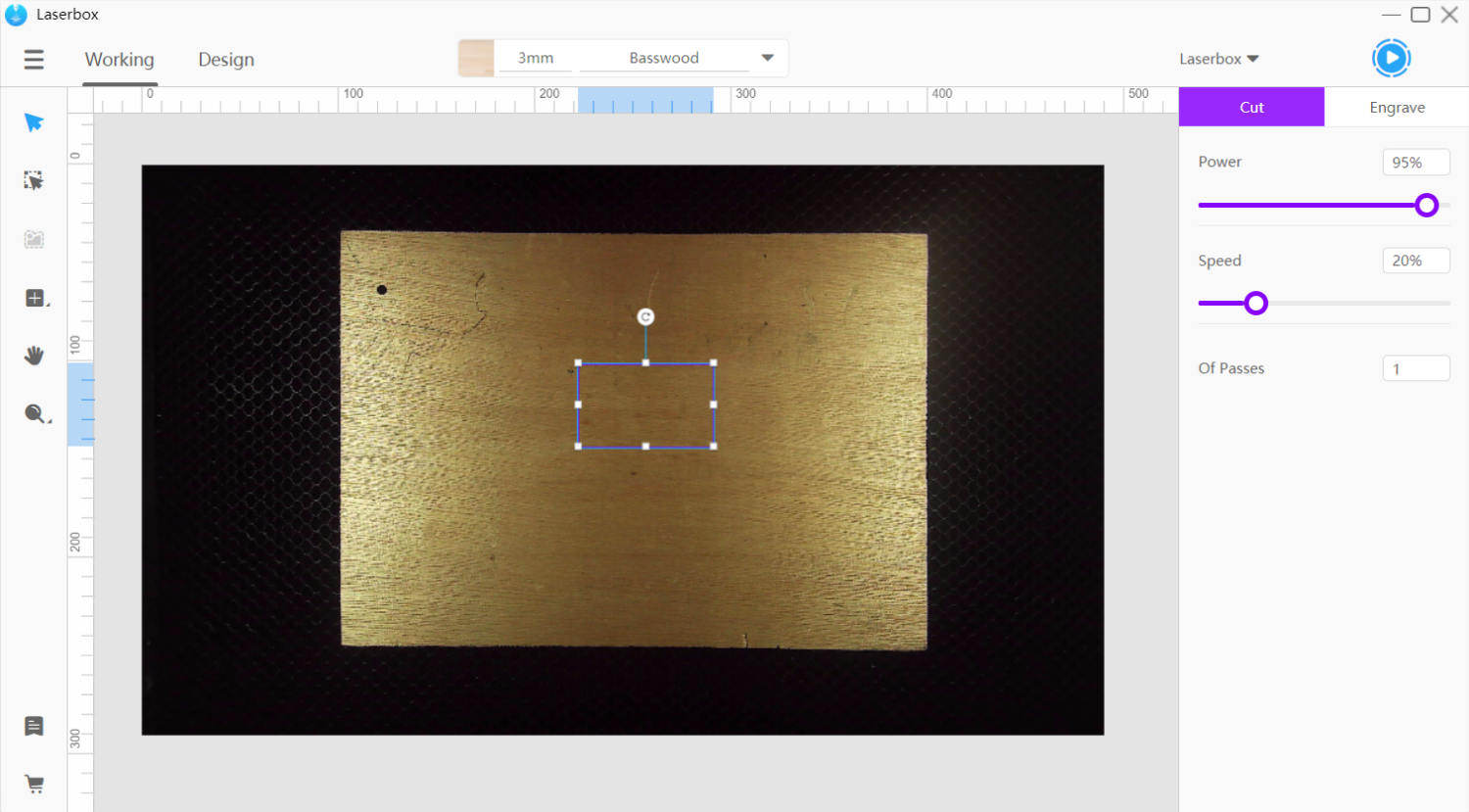
Laserbox is equipped with a high-resolution ultra-wide-angle camera. The Laserbox software relies on the camera to read the ring codes on Makeblock materials and identify the materials. If you want to process a material that is the same as a Makeblock material but without a ring code on it, you can select the material manually with the materials management tool in the software.
- View the materials list
Click the triangle icon on the right of the materials management tool to display the materials list.
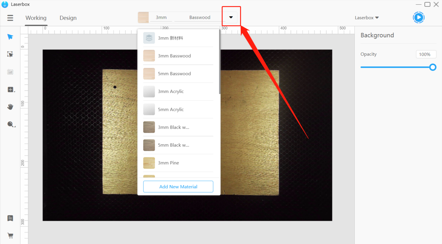
- Select a material
On the drop-down list, select the material you want to process. Laserbox will then configure the parameters accordingly.
NOTE: The processing parameters will be shown on the right side of the Working interface only when you select at least one layer on the canvas.
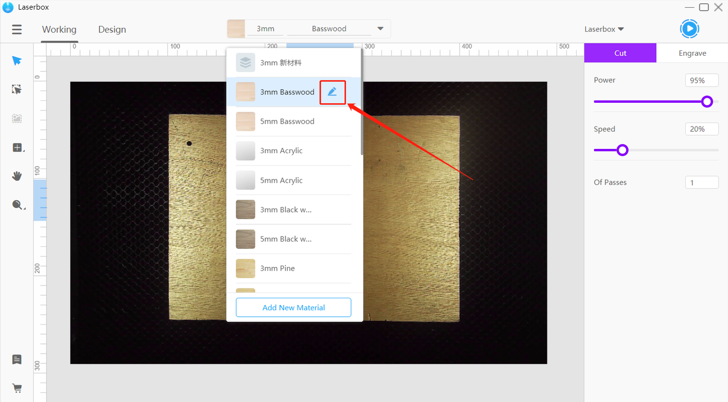
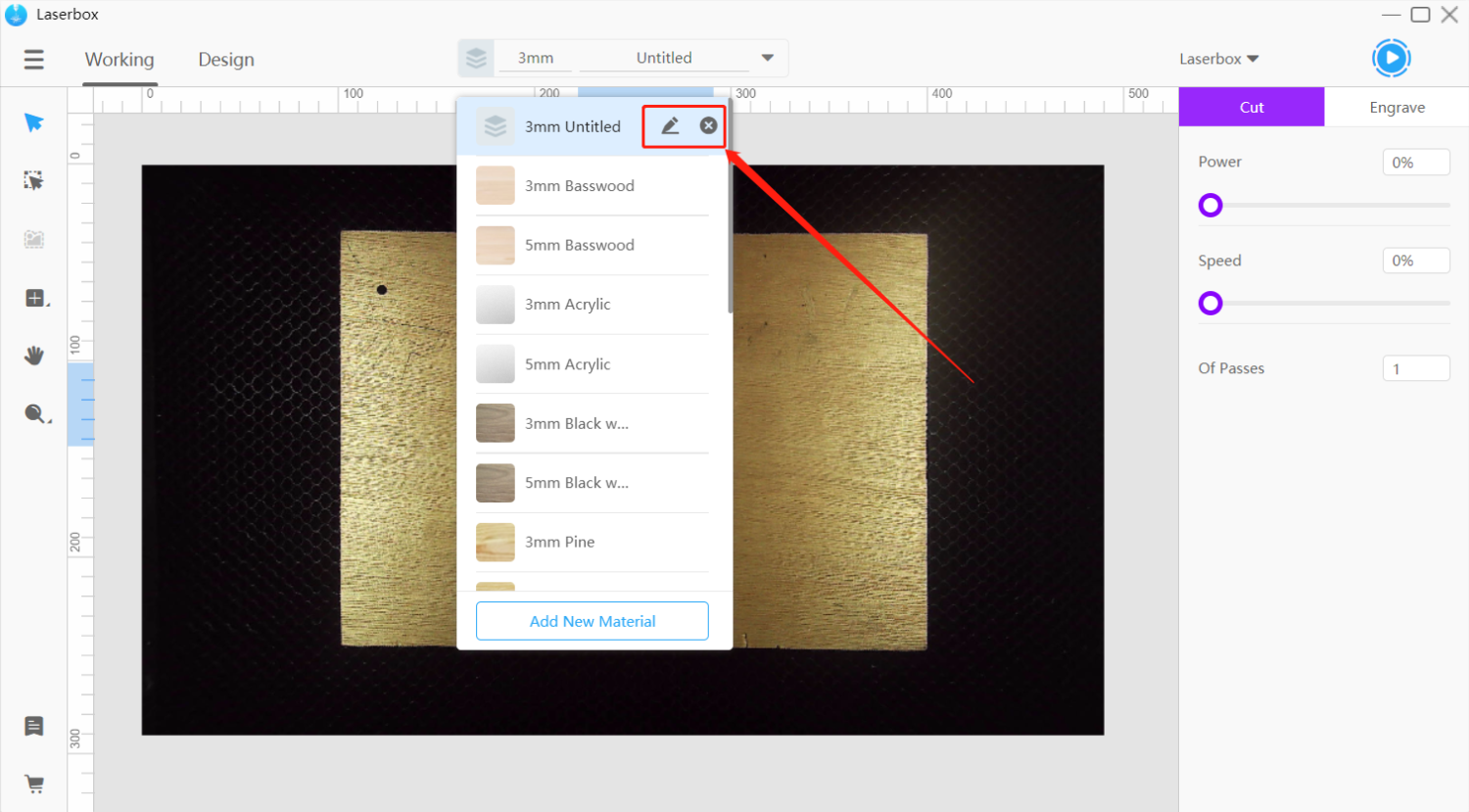
Edit material parameters
If you’re not happy with the default processing parameters and effects, change them with the materials management tool.
- Edit material
When the mouse pointer stops at a material name on the materials list, an edit button appears on the right side. Click the button to open the material editing window.
- Adjust parameters
In the Edit Material window, you can configure the laser cutting or engraving parameters for any Makeblock material.
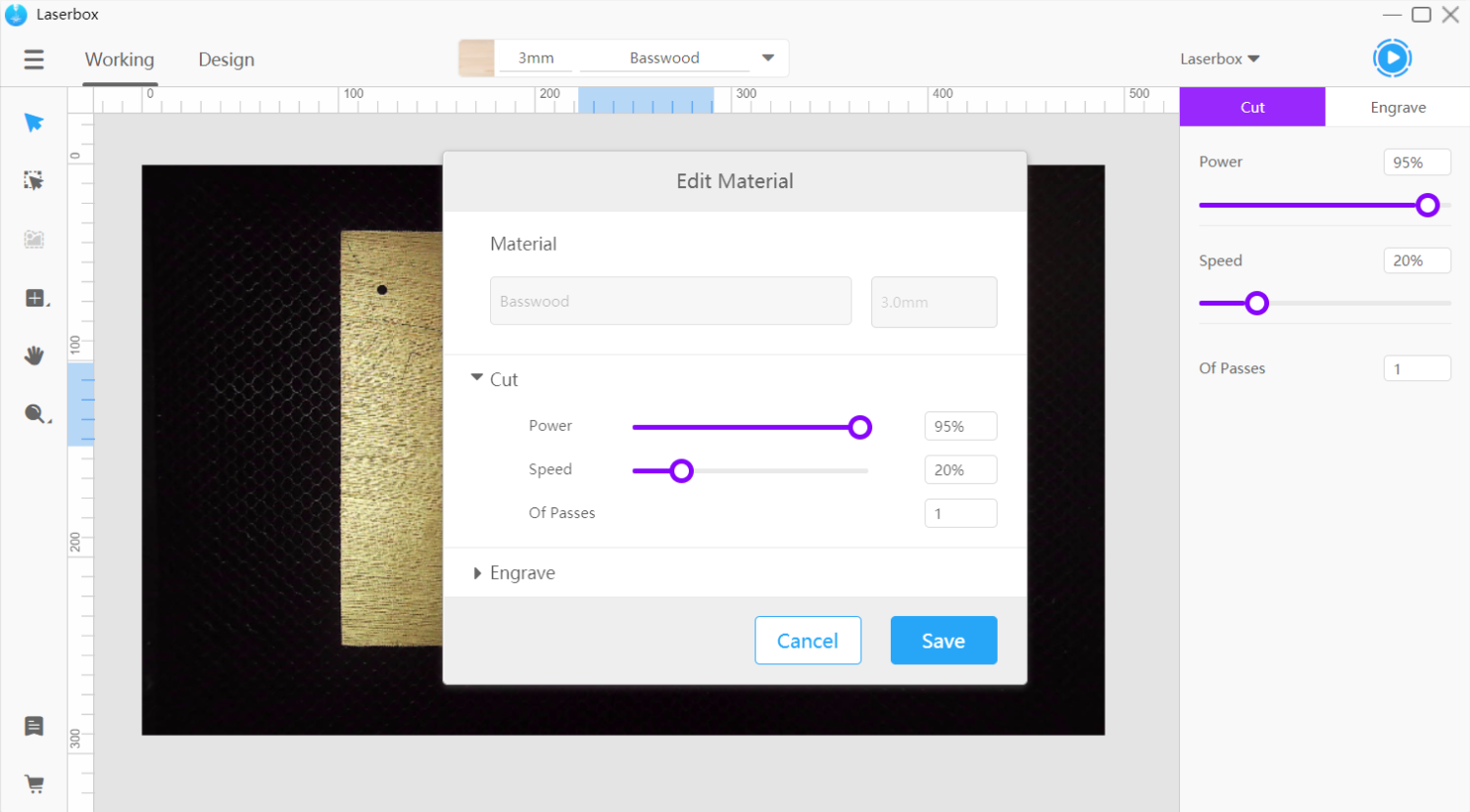
- Save parameters
Click Save at the bottom right corner of the window to apply the new parameter configuration in the software. After that, the new parameters will be applied to the same materials that are identified through the ring codes.
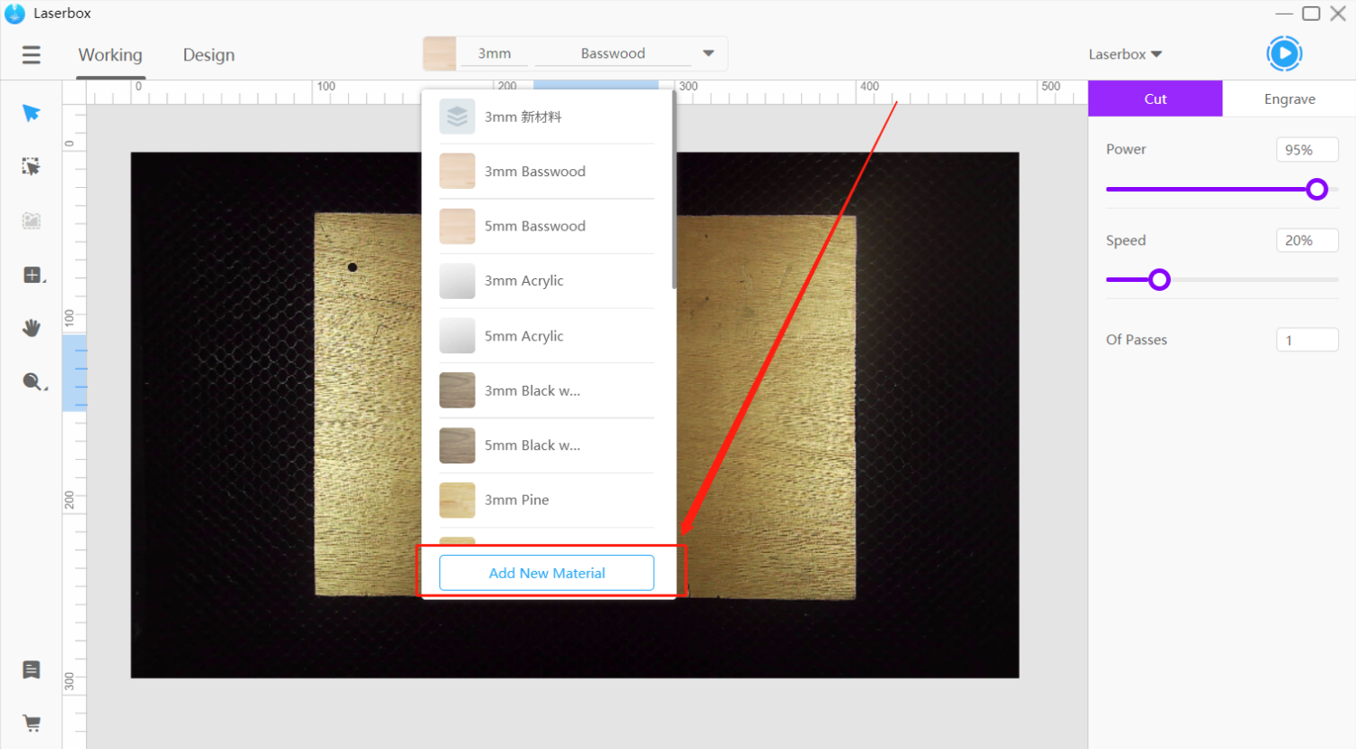
Add a new material
Non-Makeblock materials that have gone through processing parameter tests can be added to the materials list in the software. This offers quick access to parameter settings for later use.
- Add a new material
Click Add New Material at the bottom of the materials list.
- Enter material information
In the pop-up window, type in the material information, including name, thickness, engraving parameters, and cutting parameters.
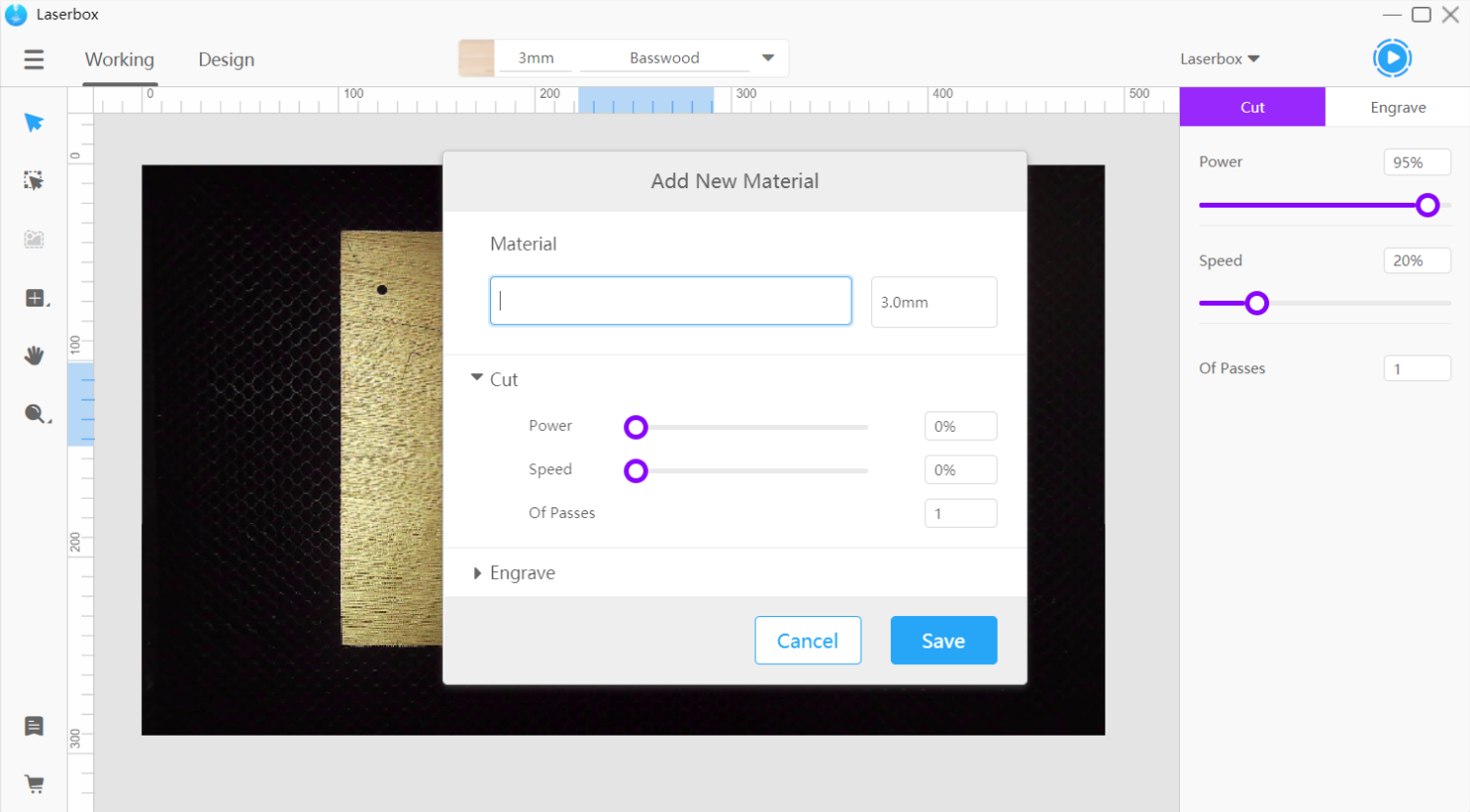
- Save material information
Click Save at the bottom right of the window. And the window automatically closes when you do this, and the materials management tool will select the new material.

- Select the material to save
The newly-added material is displayed at the top of the materials list. Click x on the right of the material name to remove the material from the list.
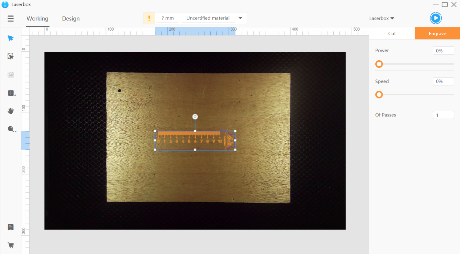
Parameter settings
Processing parameters include three types: engraving parameters, cutting parameters, and custom parameters. By default, engraving or cutting parameters will appear on the right of the Working interface after you select a layer.
Bitmap images can’t be cut, so you can only tune the engraving parameters if you select a bitmap layer.
If you select a vector layer, you can adjust both cutting and engraving parameters for it
Orange means engraving and blue for cutting.
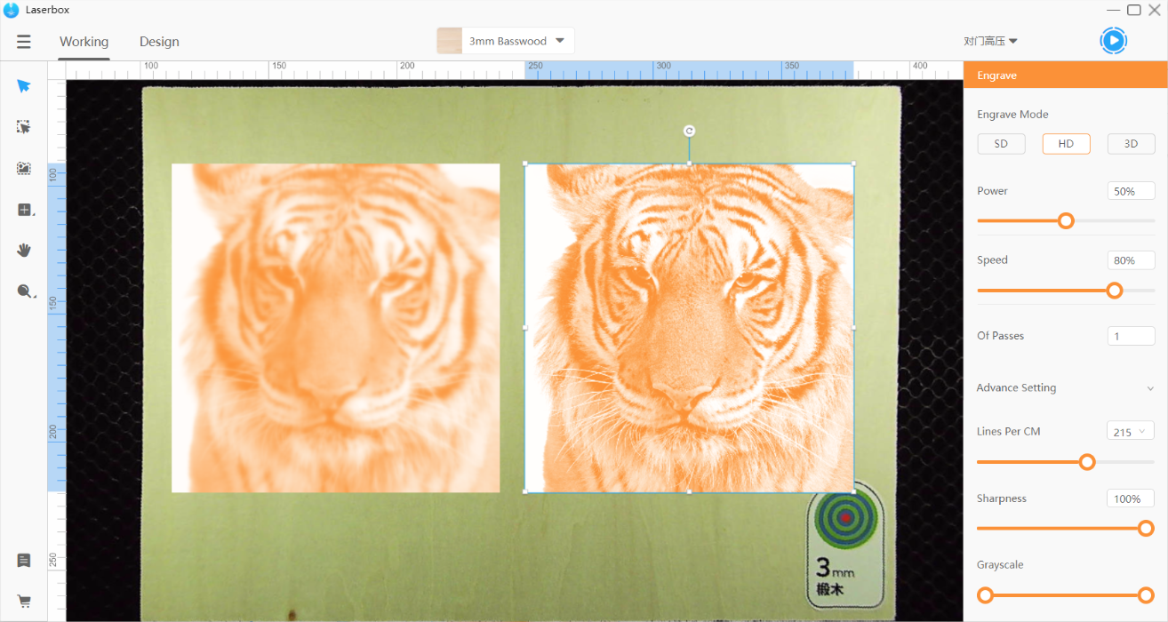
Engraving parameters
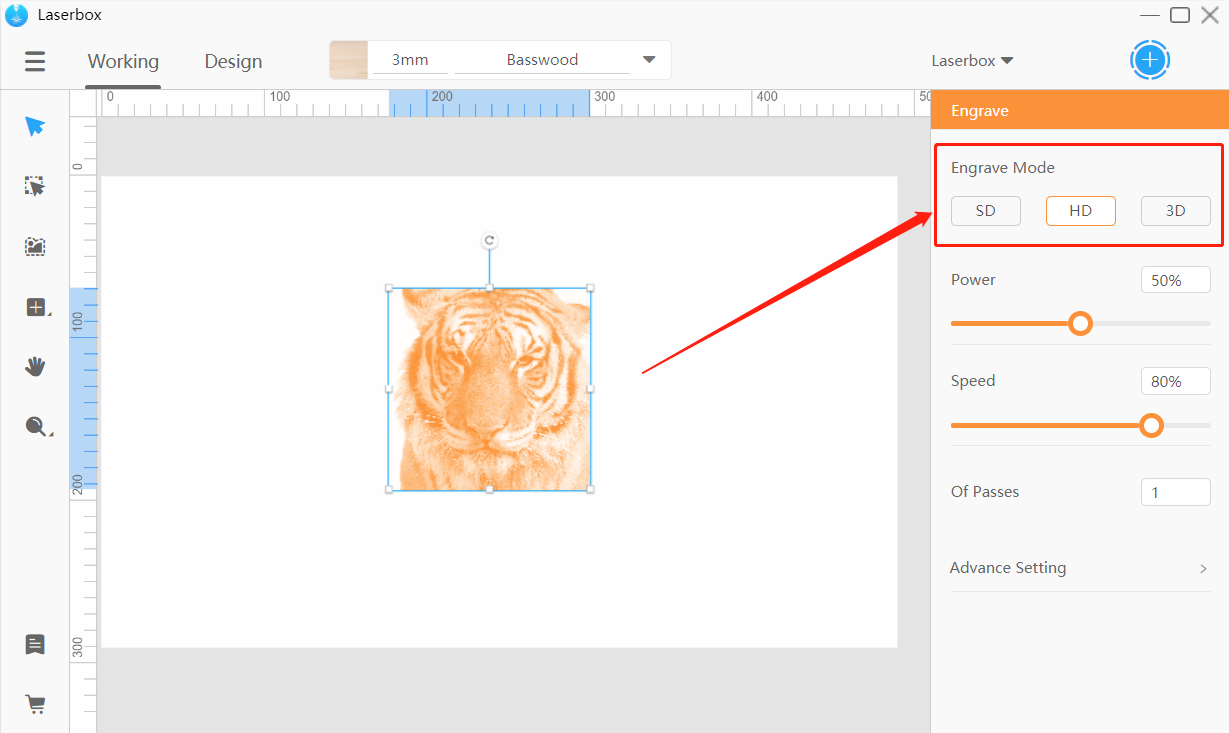
- Engrave mode
What can it do?
Engrave mode options are only available when you select a bitmap. There are three modes:
- SD Muddier engraving but shorter engraving time.
- HD Fine-carved but longer engraving time.
- 3D Generates a 3D profile based on the gray level of a bitmap. The darker the color is, the deeper the engraving will be, producing a relief effect.
How to use it?
Select a bitmap image and choose the engraving mode you want in the style panel on the right.
- Engraving power
What can it do?
Power affects engraving quality. Higher power leads to deeper engravings, and lower power means shallower engravings.
How to use it?
Select a layer and drag the slider under Power on the right side. Alternatively, type in a value to specify the power.
- Engraving speed
What can it do?
Speed also affects engraving quality. Lower speed leaves deeper engravings, and higher speed shallower engravings.
How to use it?
Select a layer and drag the slider under the speed setting on the right side. Or, enter a value in the input box to define the speed.

- Of passes
What can it do?
Of passes determines how many times a selected layer will be engraved. Multiple passes can make deeper engravings but take more time.
How to use it?
Select a layer and enter a value in the parameters panel on the right to define the number of passes. For equipment safety, the maximum number of passes supported by the software is 10.
- Lines per cm
What can it do?
Lines Per CM is only applicable to bitmap images. This parameter defines how many horizontal passes are made in one centimeter. More lines per cm can result in a finer result, but it takes longer to complete the engraving. And fewer lines per cm helps save time.
How to use it?
Select a bitmap image and go to Advance Setting in the parameters panel. Then click Lines Per CM and select a value in the drop-down menu. Optionally, drag the slider to tune the parameter.
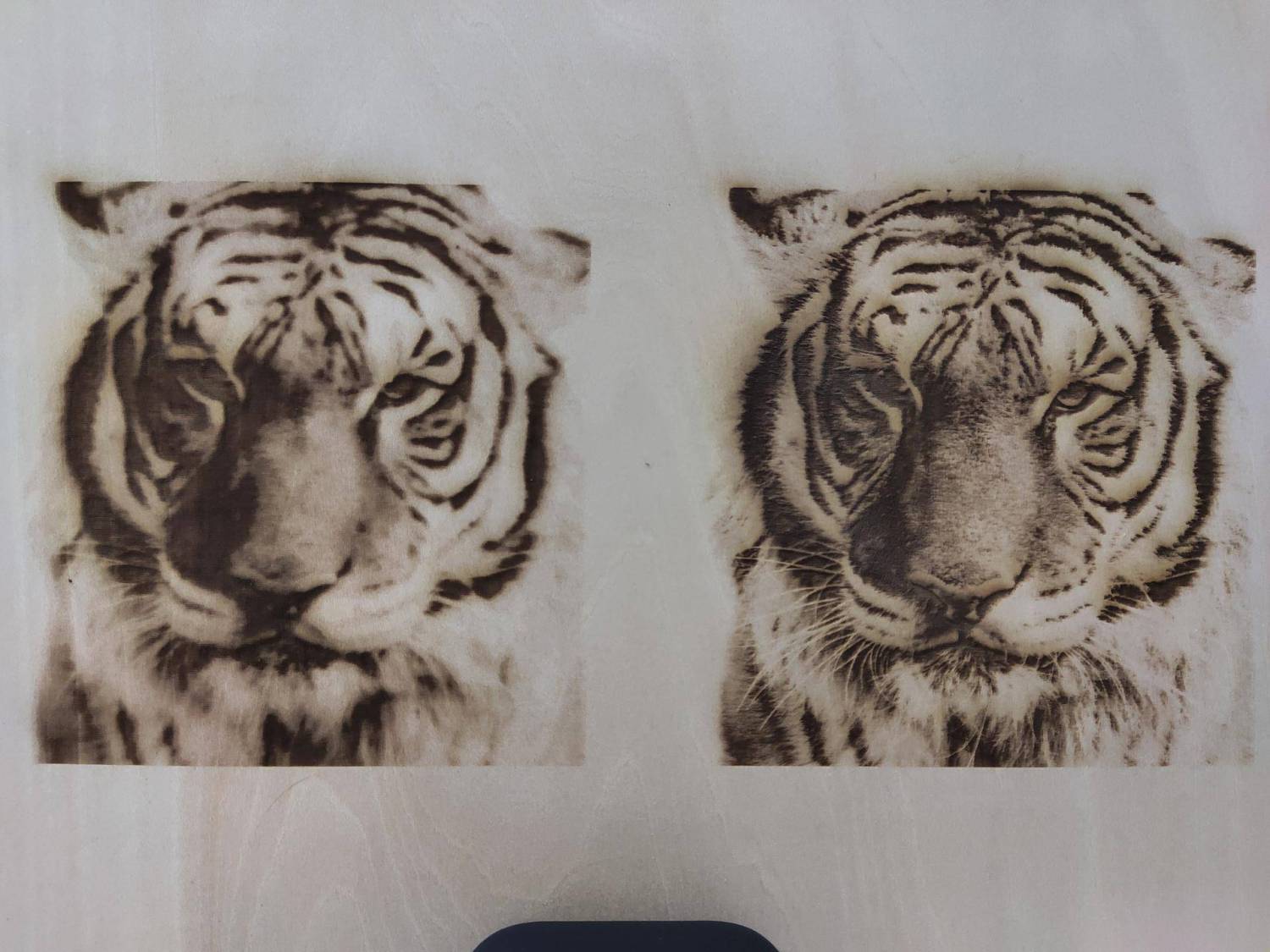
- Sharpness
What can it do?
Sharpness is only applicable to bitmap images. An image with higher sharpness has sharper edges and details, and one with lower sharpness has smoother edges and details.
The sharpness of the image on the left is 0, while the sharpness of the one on the right is 100.
How to use it?
Select a bitmap image and go to Advance Setting in the parameters panel. Then drag the slider under Sharpness or enter a value to define the parameter.

- Grayscale
What can it do?
Grayscale is only applicable to bitmap images. The grayscale option is available in the Laserbox software, allowing you to produce different engraving effects. Lower grayscale gives higher contrast but causes loss in detail.
How to use it?
To change the grayscale, select a bitmap image, then go to Advance Setting in the parameters panel, and drag the slider under Grayscale.
Cutting parameters
- Cutting power
What can it do?
Power affects cutting quality. Higher power leaves deeper cuts and lower power shallower ones.
How to use it?
In the Working interface, select a layer to cut and drag the slider under Power in the parameters panel on the right. Or, just type in a value to adjust the power.

- Cutting speed
What can it do?
Speed also affects cutting quality. Higher speed leads to narrower cuts, while lower speed causes wider cuts.
How to use it?
In the Working interface, select a layer to cut and drag the slider under Speed. Or, just type in a value to adjust the speed.
- Of passes
What can it do?
Of passes controls how many times a layer will be cut during the process. Multiple passes can produce deeper cuts and ensure the material is cut through. However, multiple passes also make the cuts wider and take more time to complete the process.
How to use it?
In the Working interface, select a layer to cut and enter a value in the parameters panel on the right. For equipment safety, the maximum number of passes supported by the software is 10.
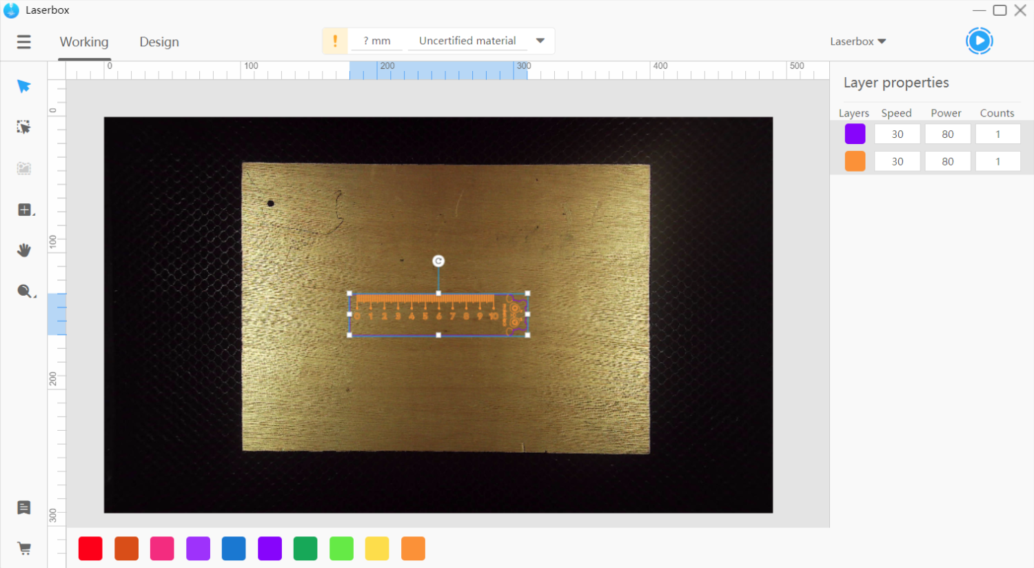
Color block mode
What can it do?
In the Laserbox software, you can sort the layers based on their colors and apply different processing parameters to layers of different colors. Tick Show Color Block in Settings to activate the mode. In the color block mode, you can configure power, speed, and number of passes without considering whether they’re for cutting or engraving.
How to use it?
Go to Menu > Settings > Software, tick Show Color Block, and click Save. To set color groups for layers, select a layer and click a color on the color block list at the bottom. A color used in the canvas will appear in the Layer properties on the right side. In the Layer properties, you can set the parameters based on colors.
Device management
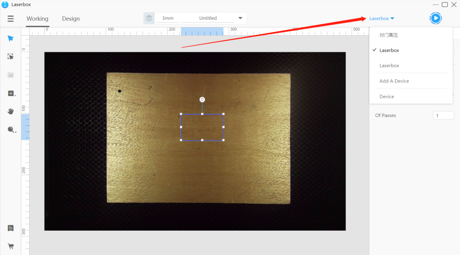
Add/Switch Devices
What can it do?
The Laserbox software allows connections to multiple Laserboxes at a time and saves the connected devices to the device list. So, you can easily switch between devices.
How to use it?
At the upper right corner of the window, find the device name and click the drop-down icon on the right of the name to show the device list.
Click on the device name to connect to the device. To remove a device from the list, put the mouse pointer on the name of an unconnected device and click × on the right.
Click Add A Device and select Connect to a new Laserbox or Connect to a networked Laserbox in the pop-up device connection window. Learn more about Connect Devices.
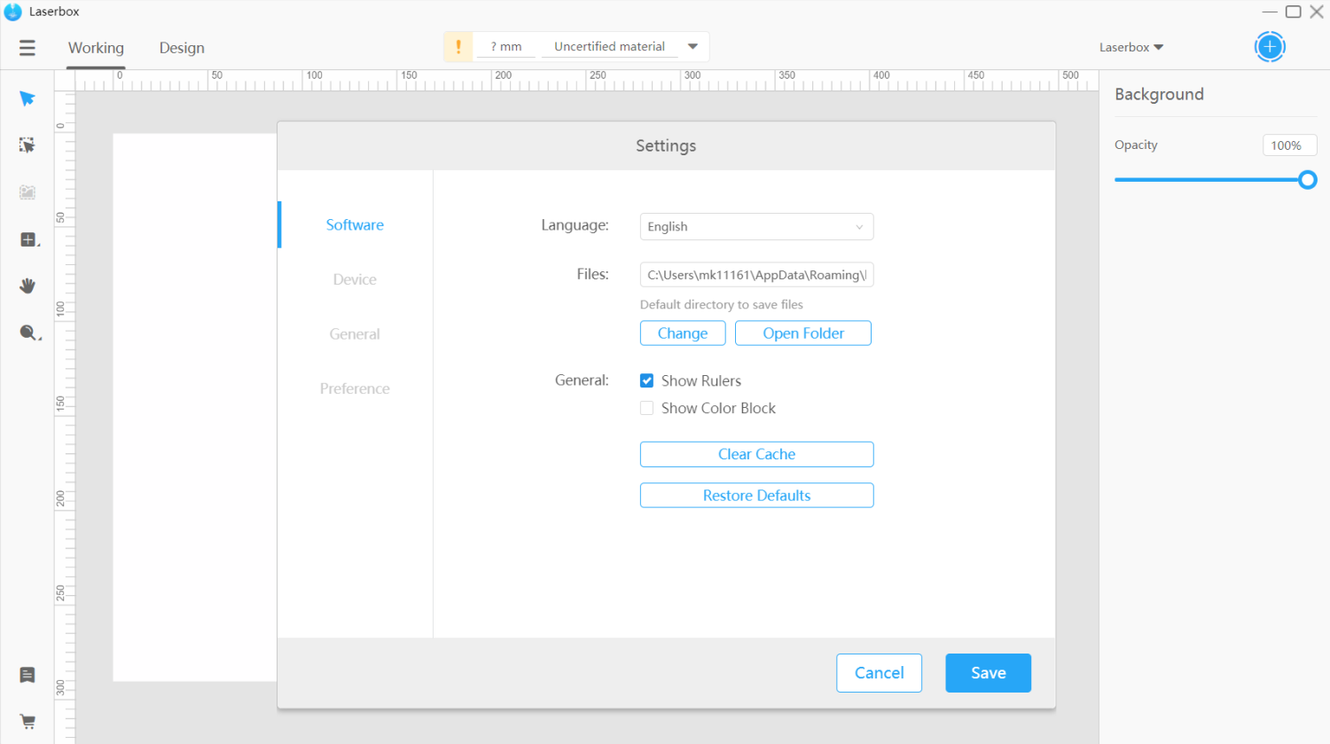
Software settings
Language settings
What can it do?
The Laserbox software has multiple display languages.
How to use it?
Go to Menu > Settings. The language option appears at the top of the pop-up window. Select a language on the drop-down list, then click Save to confirm your option. The display language will change immediately.
View/Change file locations
What can it do?
The software saves a processing file as a project. It automatically saves your file as you work. You can find your work in the recent files. So, don’t panic if you accidentally close the program before completing your work. You can view and change the default file location in Settings.
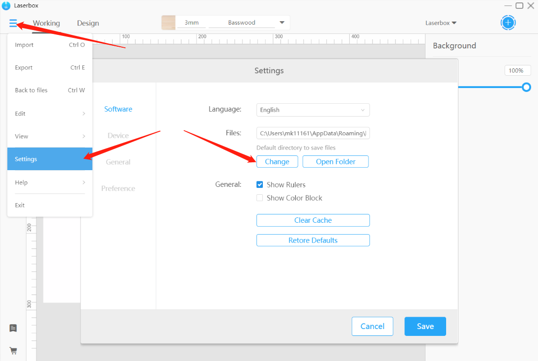
How to use it?
Go to Menu > Settings > Software and find Files. Click Change to choose a new location to save your files. Click Open Folder to view the saved files in the file manager and click Save to confirm the settings.
Show/Hide rulers
What can it do?
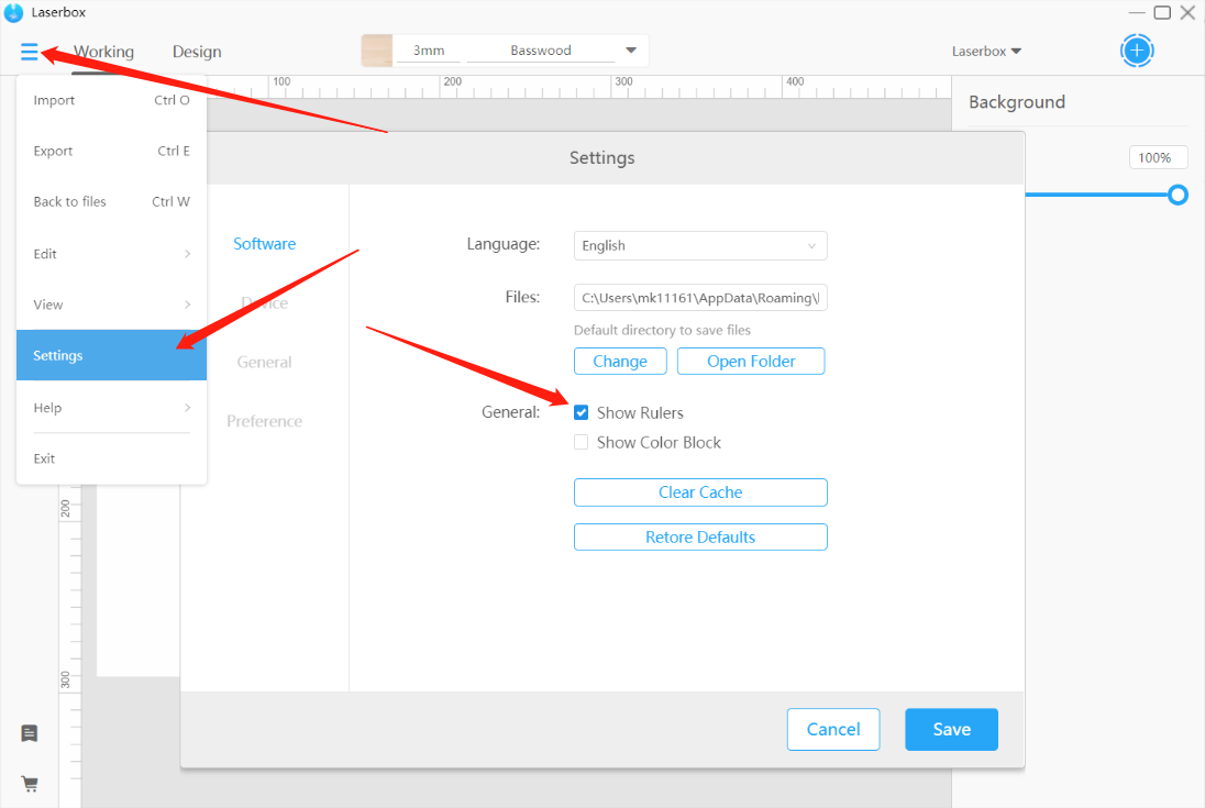
The canvas has two rulers on its edges, one horizontal and the other vertical. When you select a layer, you can see its width and height from the highlights on the rulers. The rulers tell the size and location of a layer.
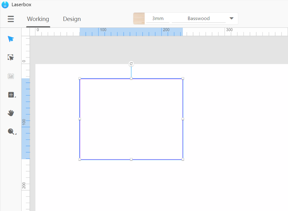
How to use it?
Go to Menu > Settings > Software and check Show Rulers. Check the box to display the rulers on the canvas and uncheck the box to hide the rulers. Click Save to confirm your option.
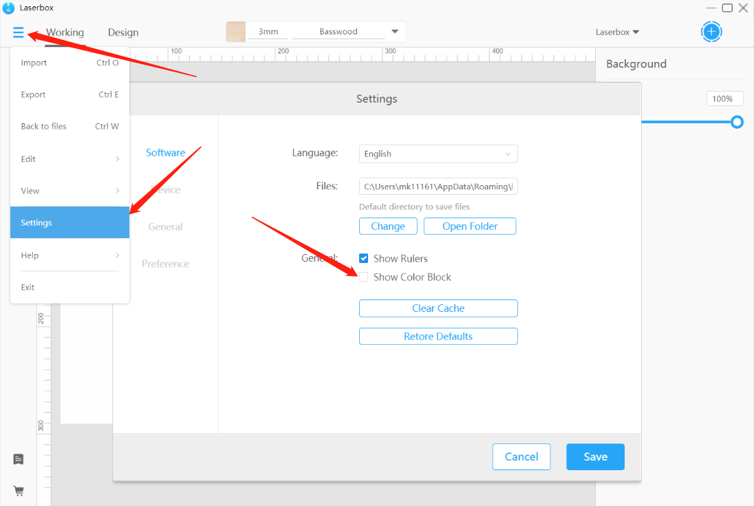
Show color block
What can it do?
The software supports grouping layers by colors and setting processing parameters for layers based on different colors. When this feature is on, you can directly set up the power and speed for your project without considering whether they’re for cutting or engraving.
默认模式 色块模式
How to use it?
Go to Menu > Settings > Software and check Show Color Block. Check the box to turn on color block mode and uncheck the box to turn it off. Click Save to confirm your settings.
Clear cache
What can it do?
The software creates some cache when in use. The cache helps enable the program to serve faster but would take up drive space. Click Clear Cache to free up space.
How to use it?
Go to Menu > Settings > Software and click Clear Cache. The software will then start clearing the cache and restart.
Restore defaults
What can it do?
This option restores the software to its default settings. If you need to reset the software after you change some settings, use this option.
How to use it?
Go to Menu > Settings > Software, click Restore Defaults, and then click Save. The software will return to the default settings.
Device settings
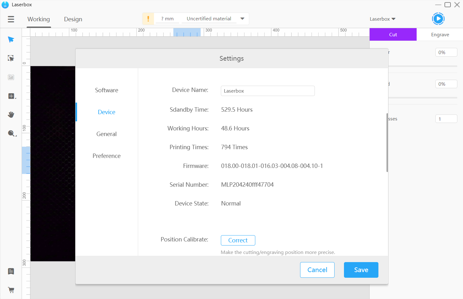
View device information
What can it do?
You can view the information about the Laserbox that is currently connected. Device information includes:
- Device Name Name of the connected device, which also appears on the left of the start button in the software interface. You can change the device name in Settings.
- Standby Time Total time that a device takes to turn on.
- Working Hours Maximum length of time that a cutting/engraving task requires.
- Printing Times Number of times that a cutting/engraving task will be carried out.
- Firmware Current firmware version.
- Serial Number Factory-applied serial number of a device.
- Device State Operation status of a device.
How to use it?
Go to Menu > Settings > Device to view device information. The Device, General, and Preference tabs are only available when a device is connected.
Position calibrate
What can it do?
The camera enables Laserbox to position design drawings and materials. When a deviation occurs, you can use Position Calibrate to reduce deviation from the visual position.
NOTE
When the laser cutter is calibrating, the A4 paper MUST be clean and flat, that is, no stains or curls, because these may hinder the camera from identifying the paper.
When the laser cutter is calibrating, DO NOT place any heavy objects on it because they may cause a positional deviation of the camera.
How to use it?
- Clean the camera
Lift Laserbox’s lid, spray some alcohol on a cleanroom wipe, and clean the camera with the wipe. Next, check whether the camera comes loose. If it comes loose, glue it to hold it in place before letting the laser cutter start calibrating.
- Connect Laserbox to your computer
Connect Laserbox to your computer and run the Laserbox software.
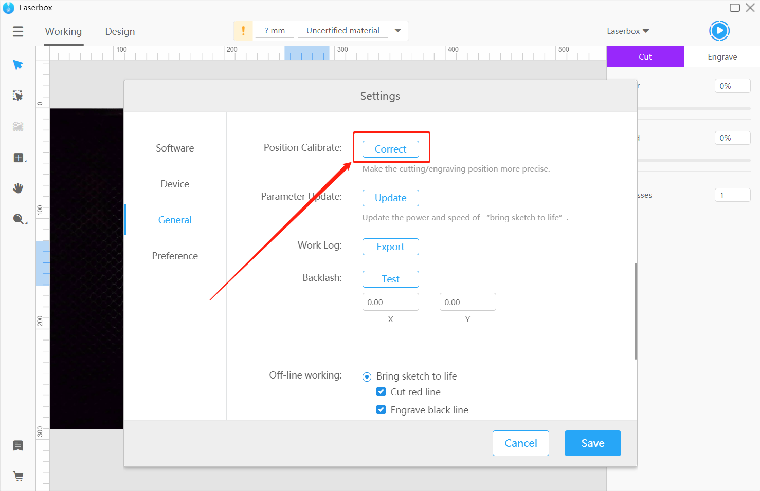
- Click position calibrate
Go to Menu > Settings > General and click Correct after Position Calibrate. Then you will see a pop-up window as follows.
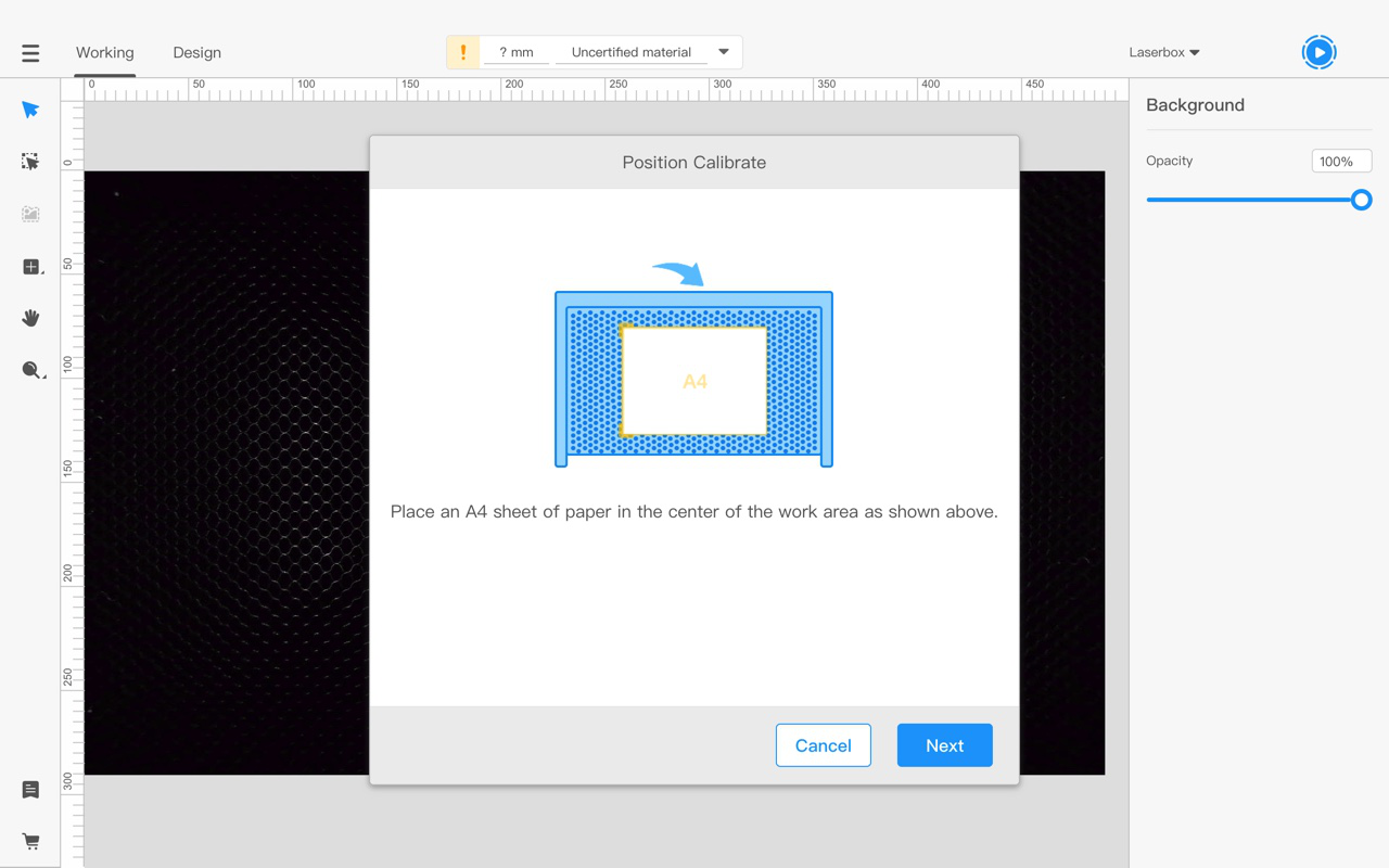
- Put in A4 paper
Follow the software prompts to place the A4 paper.Use a glue stick or double-sided tape to avoid curls on the paper edges.
- Start calibrating
Click Next in the prompt pop-up window and press the button on the laser cutter to start the calibration. It takes about three minutes to complete the calibration.
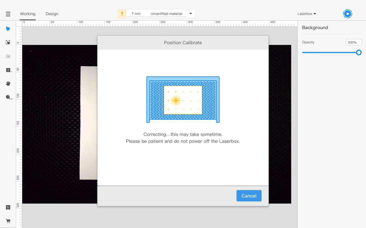
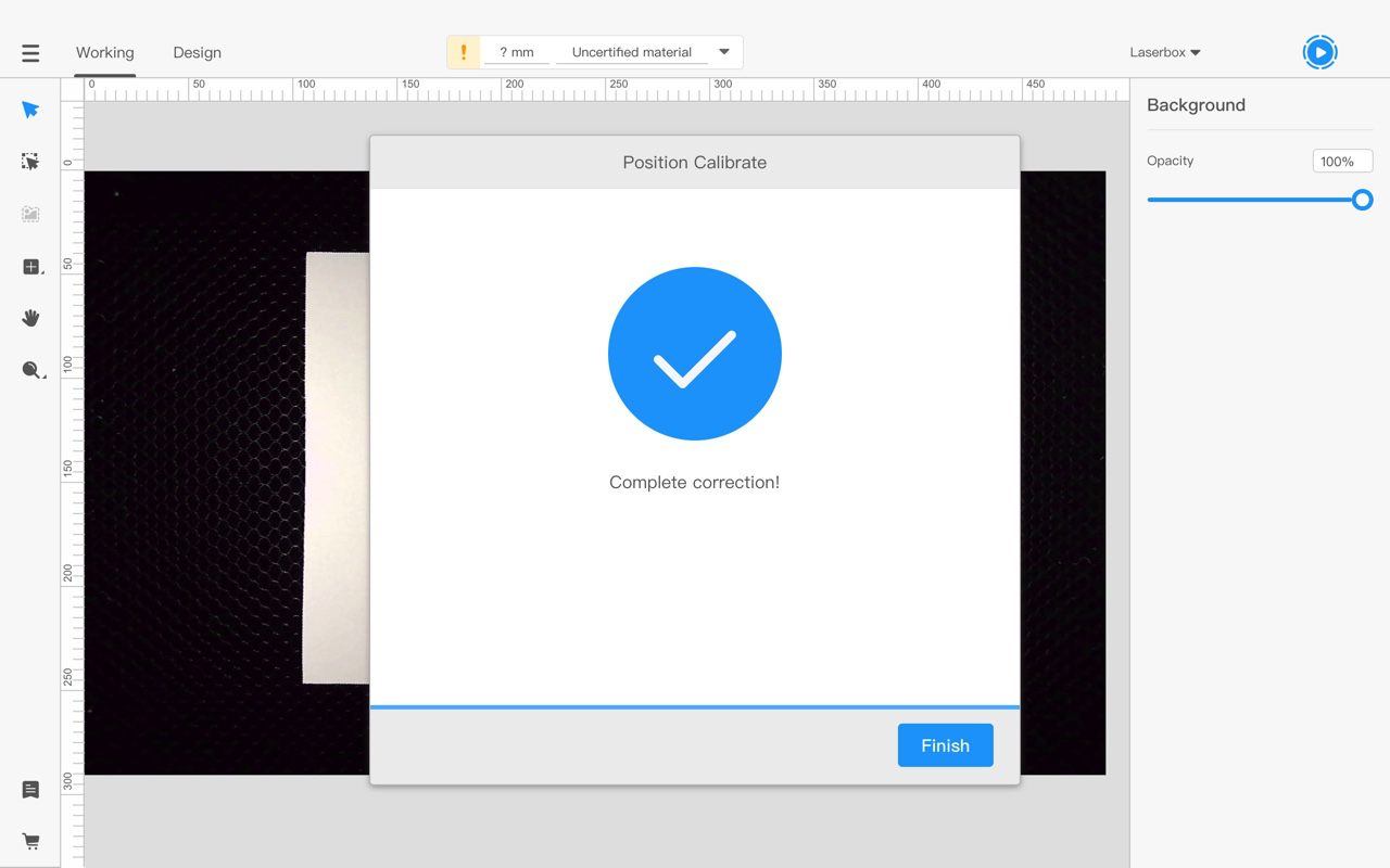
- Calibration completes
A window below pops up when the calibration is done.
Parameter update
What can it do?
Laserbox boasts multiple offline features, which empower it to identify Makeblock materials and set parameters when the laser cutter is offline. Parameter Update synchronizes the material list and processing parameters in the software into Laserbox, allowing the laser cutter to apply new parameter settings when used offline. Learn more about Materials Management.
How to use it?
Connect Laserbox to your computer. To sync the parameter settings to the laser cutter, in the software, go to Menu > Settings > General, and click Update after Parameter Update.
Export work logs
What can it do?
When errors occur to Laserbox, they will be recorded in the work log. Exporting the work log and sending it to our after-sales engineers help us analyze the problem quickly.
How to use it?
Go to Menu > Settings > General and click Export after Work Log. Wait for a few seconds to let the computer save the work log.
Detection settings
What can it do?
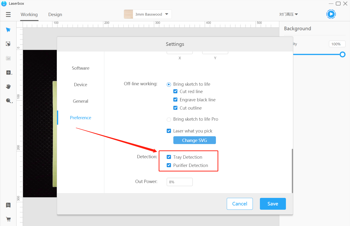
Laserbox can perform device detection, checking whether the tray or purifier is correctly installed. By default, Tray Detection is off and Purifier Detection is on. When Tray Detection is on, the software will display a prompt if the tray isn’t properly installed. Likewise, when Purifier Detection is on, a prompt pops up in the software if the purifier isn’t properly installed or the filter cartridge is clogged.
How to use it?
Go to Menu > Settings > Preference and check the options under Detection to turn on the features. If you want to turn off the detection, uncheck the options.
Out power
What can it do?
Out power refers to the minimum duty cycle of laser emission. The laser isn’t emitted continuously but at intervals in a specific cycle. The fraction of time of laser emission during a cycle is duty cycle. When the duty cycle is lower than a certain value, the lasers fail to come out. Out Power allows you to set the minimum duty cycle to ensure the normal laser emission. After Laserbox operates for a long time, a certain level of power loss occurs. In this case, increase Out Power to offset the loss.
NOTE: Adjust Out Power only when the laser emission goes wrong.
How to use it?
Go to Menu > Settings > Preference, enter a value in the input box to adjust the minimum Out Power.
Firmware/Software updates
What can it do?
The Laserbox software and firmware will be updated on an irregular basis to provide you with more features and better user experience. Check for updates in the software, and update the software and firmware to the latest version.
How to use it?
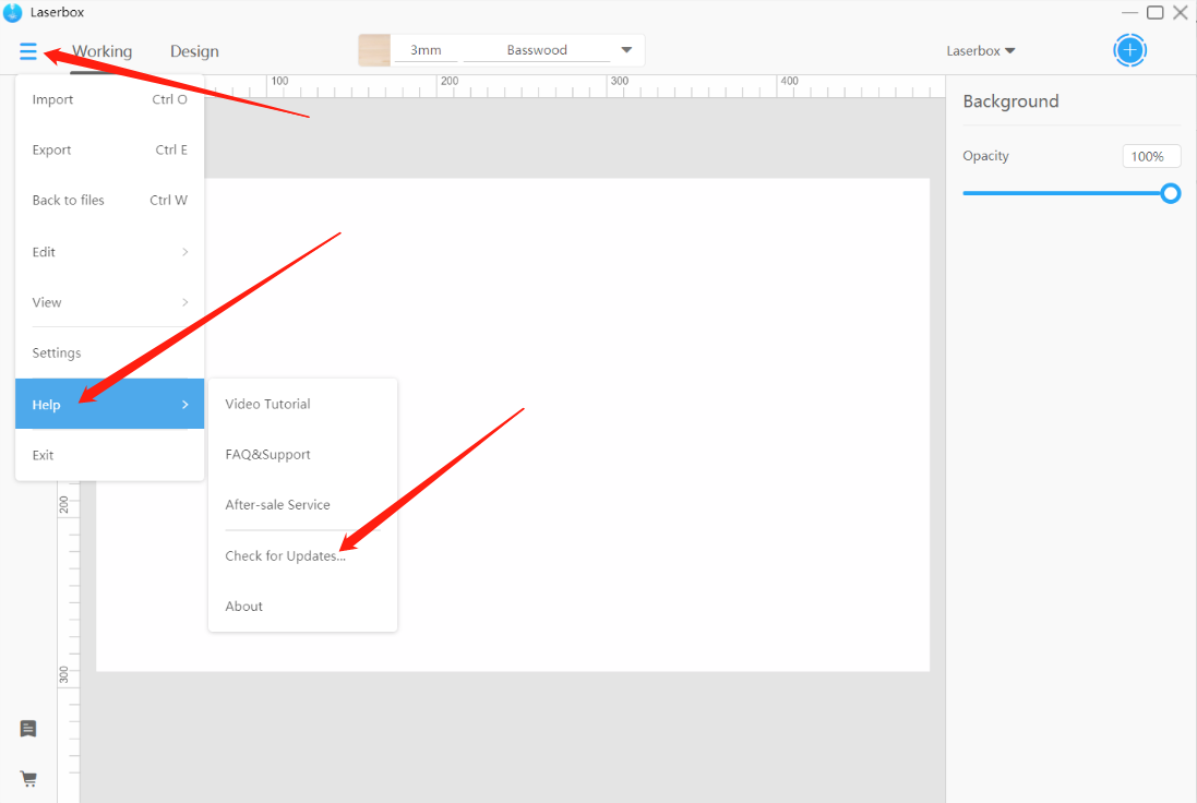
- Check for updates
Go to Menu > Help > Check For Updates… to see whether the software and firmware are in the latest version.
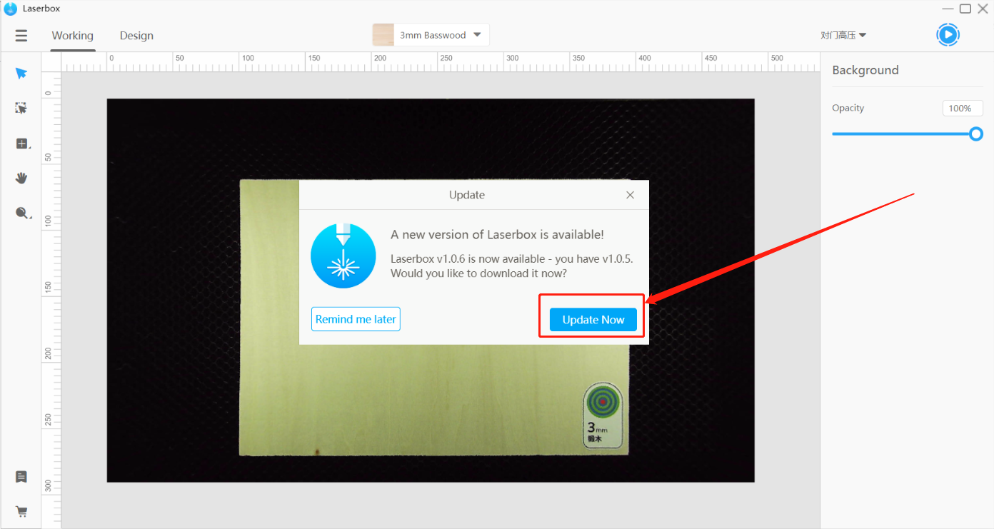
- Update software
2.1 Click to update
When a new version of the software is released, a prompt below will pop up. Click Update Now to download the latest version.
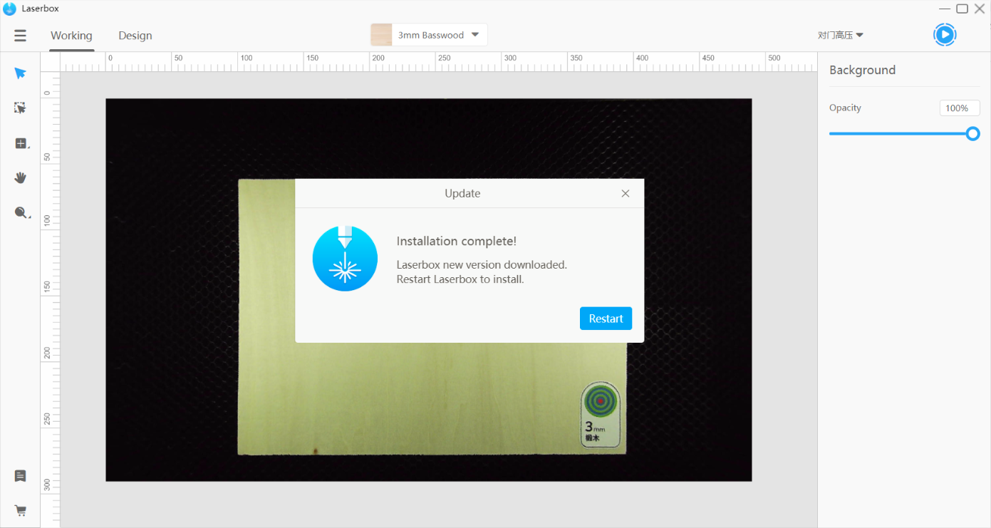
2.2 Restart the software
When the installation is complete, click Restart to complete the software update and open the latest version.
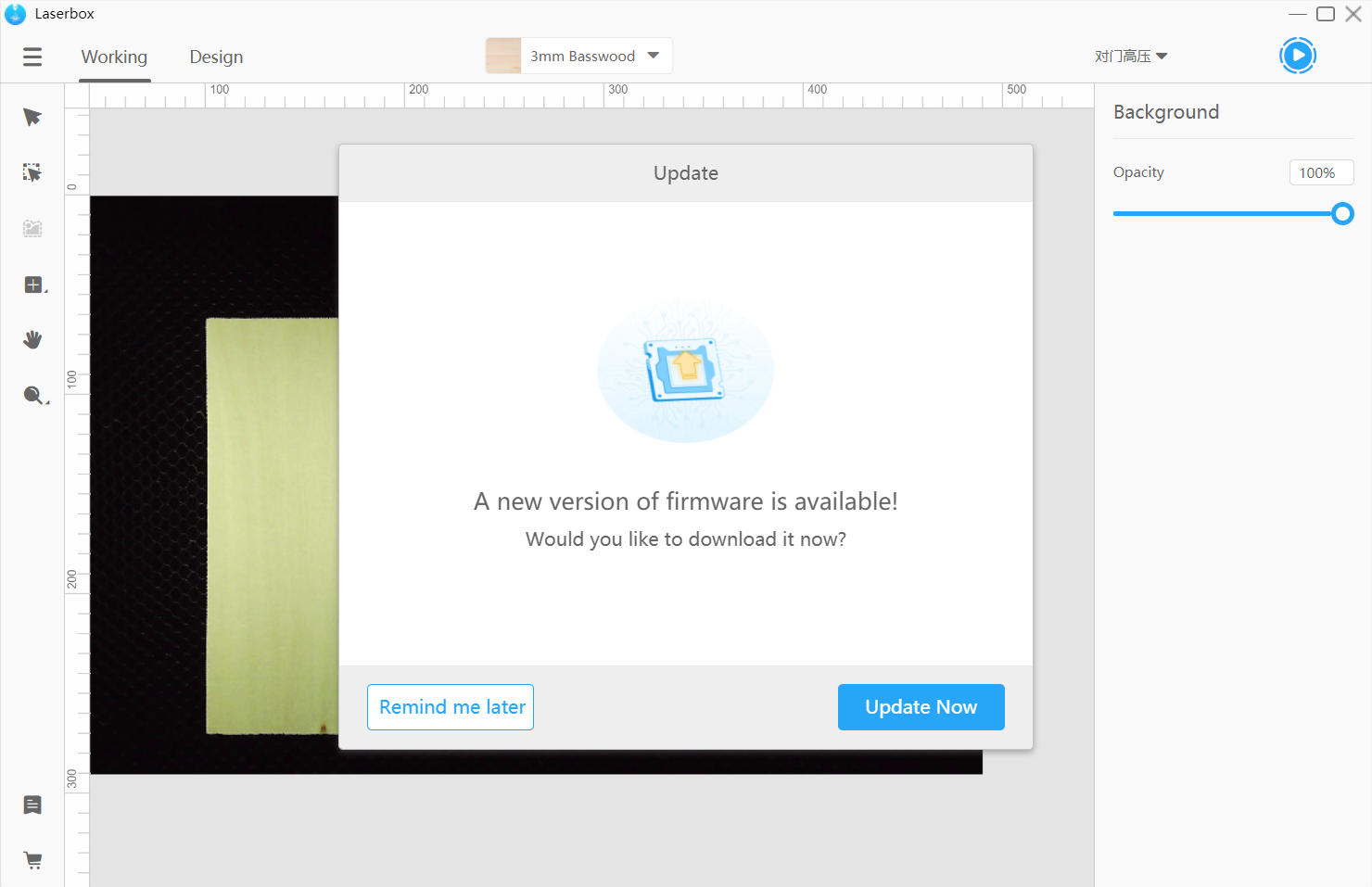
- Update firmware
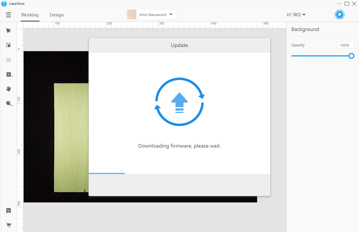
3.1 Click to update
When a new version of firmware is available, a prompt below will pop up. Click Update Now to download and install the latest version.
Closing the software or turning off the laser cutter in the middle of the update installation may cause a failed update or Laserbox unable to operate. So, wait for the firmware update to complete.
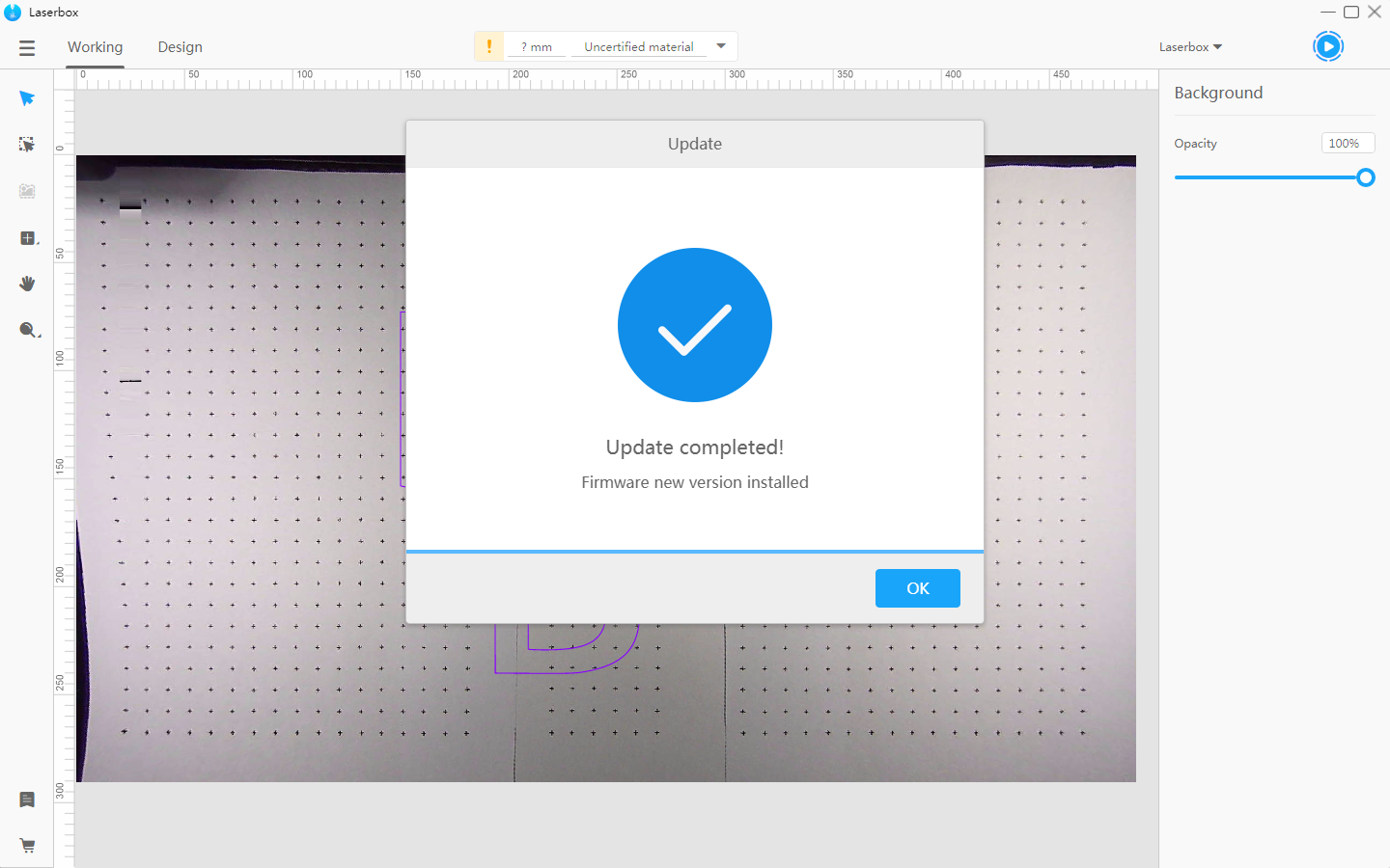
3.2 Finish
When the update is complete, a window below pops up.