How Can We Help?
Me Line Follower
Overview
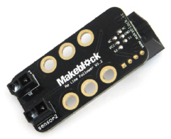
The line follower module is designed for line following robots. There are two sensors, each with an IR transmitting LED and an IR static induction phototransistor. mBot Ranger can move along a black line on a white background or a white line on a black background. It features fast detection and simple circuits. The blue tag on the interface of this module indicates that it is a dual digital interface and that it should be connected to a port with the blue tag on the main control board.
Specifications
● Operating temperature: 0–70℃
● Control mode: Dual digital interface
● Dimensions (L x W x H): 51 mm x 24 mm x 22 mm
Features
● The white zone on the module is for connection with metal beams;
● The two LED indicators report the line following status;
● Reverse connection of power does no harm to the IC;
● The module is susceptible to natural light, so it may not perform well in places where the ambient light varies greatly;
● The module supports programming in Arduino IDE, and simplifies the programming process with a runtime library;
● The module supports block-based coding on mBlock 5 and mBlock 3, which is suitable for all ages;
● The connection is easy with RJ25 connectors;
● The module features modular installation, compatible with Lego parts;
● The module has pins S1, S2, VCC, and GND, which supports most Arduino main control boards.
Pin definition
The connector of the line follower module has 4 pins. The features of the pins are shown in the following table.
| SN | Pin | Feature |
| 1 | GND | Connect the ground electrode |
| 2 | VCC | Connect the power cord |
| 3 | S1 | Output the data of sensor 1 |
| 4 | S2 | Output the data of sensor 2 |
Wiring mode
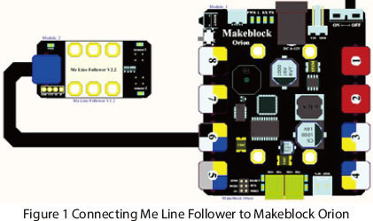
The tag color on the interface of the line follower sensor is blue. When you use an RJ25 connector, you need to connect it to a port with the blue tag on the main control board. Take Makeblock Orion as an example. You can connect it to port 3, port 4, port 5, or port 6 as shown in the following figure.
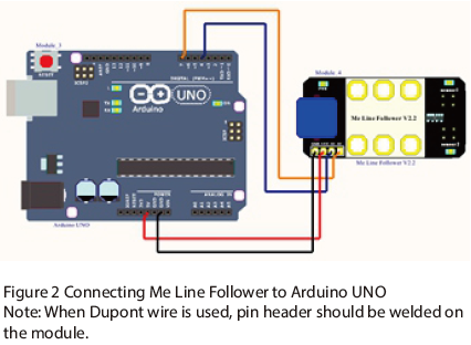
When you use a Dupont cable to connect to Arduino Uno, pin S1 and pin S2 of the module should be connected to digital interfaces as shown in the following figure.
Programming guide
The line follower module supports programming with mBlock 5. The following is a brief description of a block on this module:
| Block | Features |
 |
Select a port |
The line follower module supports programming with mBlock 3. The following is a brief description of a block on this module:
| Block | Features |
| Select a port |
If you program in Arduino, you need to use Makeblock-Library-master to control the line follower module.
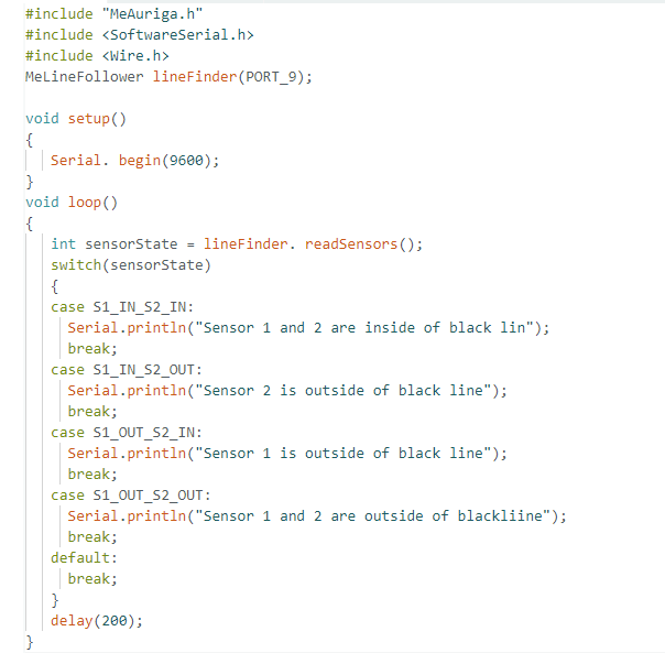
MeLineFollower(uint8_t port) defines the port to be connected:
| Function | Feature |
| MeLineFollower(uint8_t port) | Define the port to be connected |
| uint8_t readSensors() | Read the status values of the sensors |
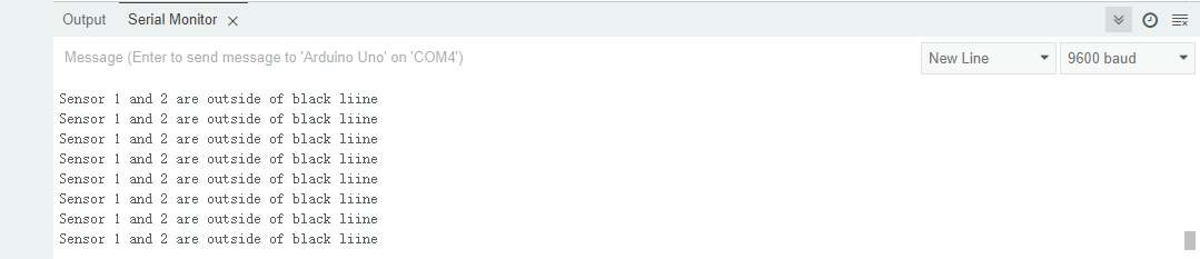
This program is written in Arduino programming language. The values of the sensors are read every 200ms. You can see if the two sensors are outside of the black line from the serial monitor.
Working principle
The line follower module is a robotic part developed according to the principle of reflective photoelectric sensor. Since IR has different reflection strength on objects with different colors, infrared light can be continuously emitted to the floor when mBot Ranger is moving. When infrared light is emitted to a white paper floor, diffuse reflection occurs, and the reflected light is absorbed by the absorption tube installed on mBot Ranger. When infrared light meets a black line, it is absorbed, and no reflected light is absorbed by the absorption tube installed on mBot Ranger. The position of the black line and the moving path of the mBot Ranger are determined by whether there is reflected light absorbed by the absorption tube. The output value of the line follower sensor is 0 when a black line is detected, and the output value is 1 when a white line is detected.
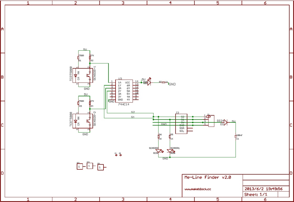
Schematic
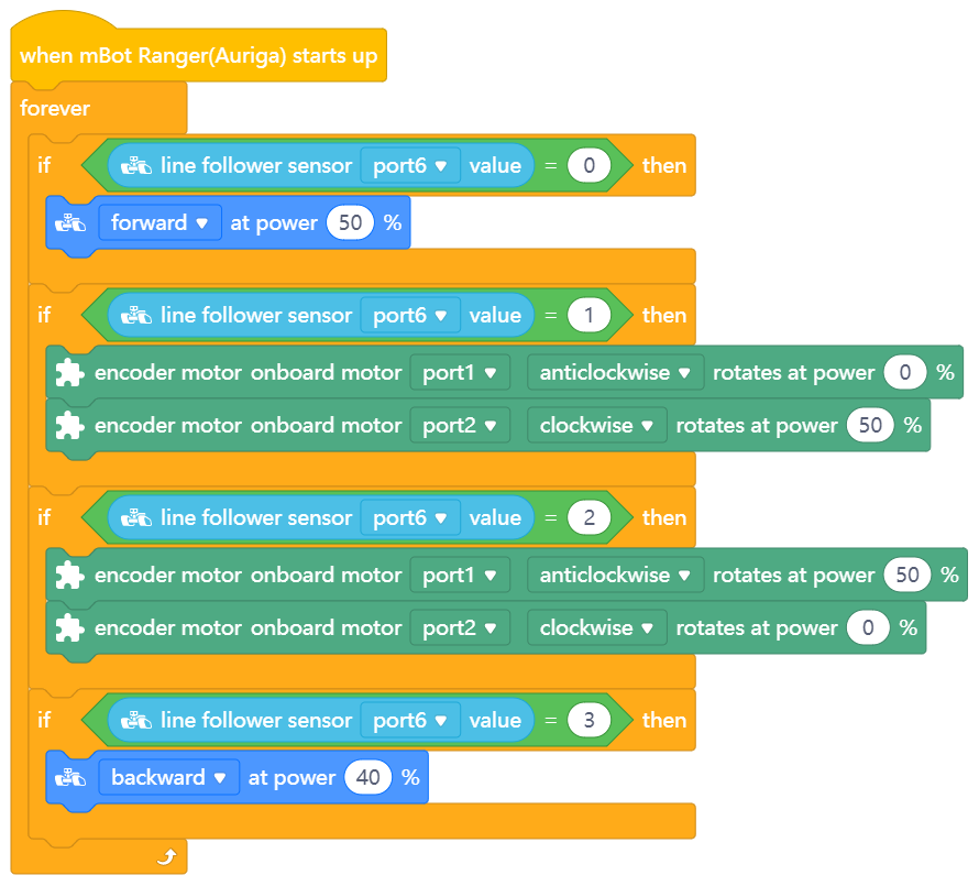
Line follower program on mBlock 5
The following figure shows a line follower program on mBlock 5, achieving the line following effect through the detection by the infrared probes. The output value is 0 when the line follower sensor detects a black line, and the output value is 1 when it detects a white line.